
Solution distribution arrangement for a cleaning machine

a technology for cleaning machines and distribution arrangements, which is applied in the direction of vacuum cleaners, floor scrubbing machines, carpet cleaners, etc., can solve the problems of insignificant effect of liquid level on flow rate, increased pumping cost, and reduced flow rate out of the tank

Inactive Publication Date: 2007-09-18
HEALTHY GAIN INVESTMENTS
View PDF8 Cites 10 Cited by
  • Summary
  • Abstract
  • Description
  • Claims
  • Application Information

AI Technical Summary

Benefits of technology

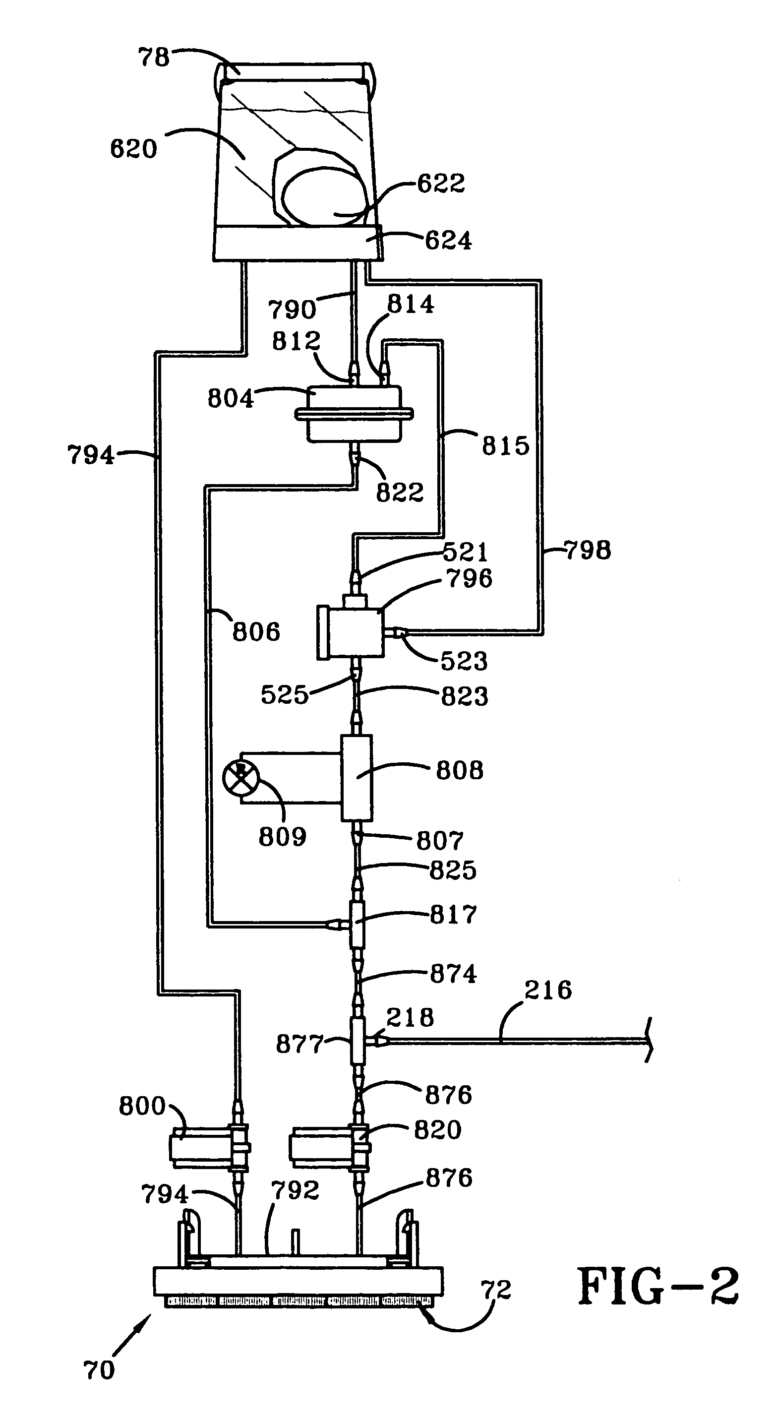
[0006]The foregoing and other objects of the present invention will be readily apparent from the following description and the attached drawings. In one aspect of the invention, a portable cleaning apparatus for cleaning a surface in which cleaning solution is dispensed to the surface and substantially simultaneously extracted along with the dirt on the surface in a continuous operation is provided. The portable cleaning apparatus includes a housing and a distributor operatively connected to the housing for distributing cleaning solution to the surface. A first solution container is removably mounted to the housing and fluidly connected to the distributor for supplying a flow of cleaning solution to the distributor. A recovery tank is removably mounted to the housing and a suction nozzle is secured to the housing and in fluid communication with the recovery tank for transporting the cleaning solution and dirt from the surface into the recovery tank. A suction source is in fluid communication with the suction nozzle and recovery tank for drawing the cleaning solution and dirt from the surface through the suction nozzle and to the recovery tank. A second solution container is provided inside the first solution container for supplying a flow of cleaning solution to the distributor.

Problems solved by technology

However, as the level of the water and detergent lowers during the application of cleaning solution in a gravity flow system, the flow rates out of the tanks will decline and at disproportional rates from each other due to the different tank volumes.
One solution is to pump the fluids from their respective tanks at a pressure that is much higher than the hydrostatic head, thus making the effect of the liquid level on flow rate insignificant.
However, the pump is an added cost, consumes power, and is subject to failure.

Method used


Image

  • Solution distribution arrangement for a cleaning machine
  • Solution distribution arrangement for a cleaning machine
  • Solution distribution arrangement for a cleaning machine

Examples


Embodiment Construction

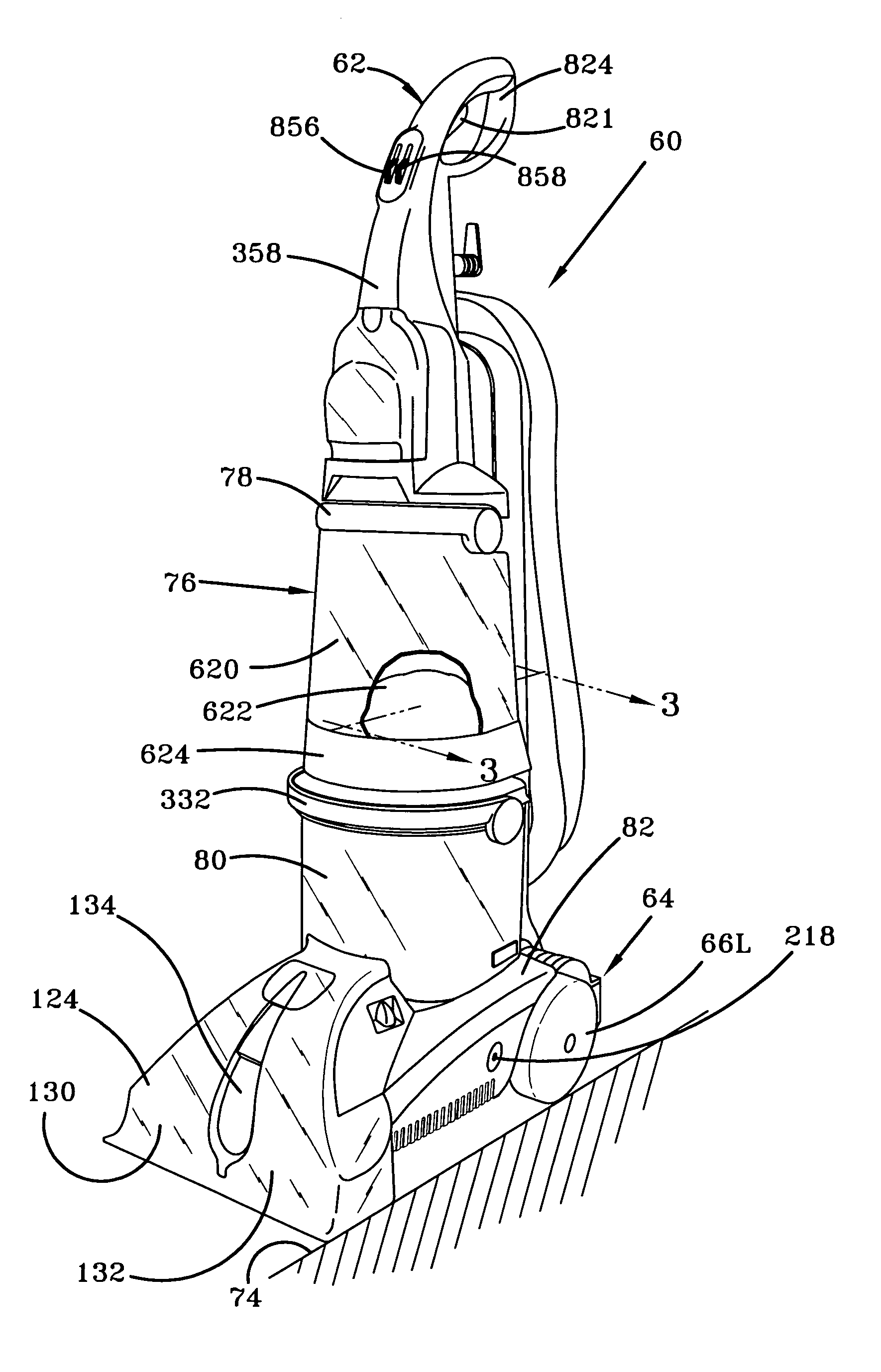
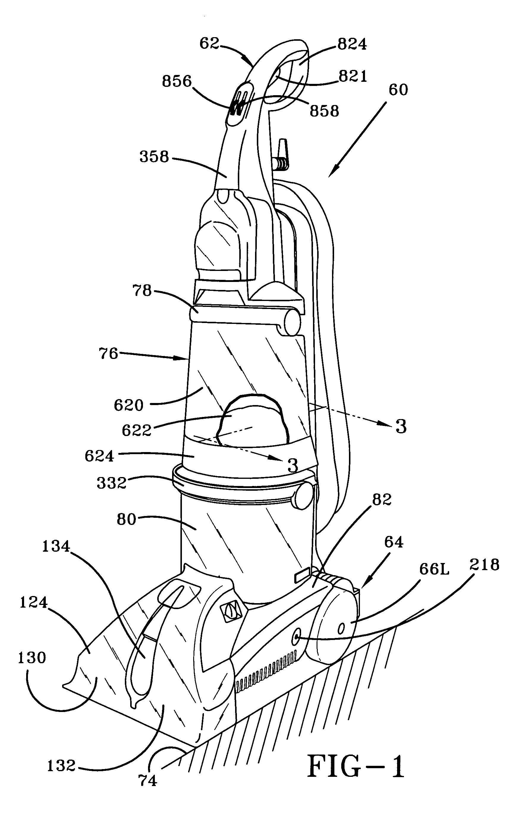
[0014]Referring to the drawings, FIG. 1 depicts a perspective view of a cleaning apparatus in the form of an upright carpet extractor 60 according to one embodiment of the present invention. The upright carpet extractor 60 comprises an upright handle assembly 62 pivotally connected to the rear portion of the floor-engaging portion of base assembly 64 that moves and cleans along a surface 74 such as a carpet. The base assembly 64 includes two laterally displaced wheels 66 (only the left wheel 66L being shown) rotatably attached thereto. A supply or solution tank assembly 76 is secured upon a bottom base 624 and removably mounted to the handle portion 62 of the extractor 60. A combined air / water separator and recovery tank 80 with carrying handle 332 removably sets atop a motor / fan assembly 90 (FIG. 3 from the copending published application having publication no. 20030226230, the disclosure being incorporated herein by reference) of base assembly 64 and is surrounded by a hood portio...


PUM


Abstract

A portable cleaning apparatus for cleaning a surface is provided and includes a housing. A distributor is operatively connected to the housing for distributing solution to the surface. A first solution container is mounted to the housing and contains a first solution. The first solution container has a bottom portion with an outlet portion fluidly connected to the distributor for supplying a flow of a first solution to the distributor. A second solution container with an outlet is provided in the first solution container and contains a second solution. The outlet of the second solution container is fluidly connected to the distributor for supplying a flow of a second solution to the distributor. In at least one aspect of the invention, the second solution container is design and constructed to transfer the weight of the first solution above the second solution container to the second solution in the second solution container to produce substantially the same hydrostatic head at both the outlet of the first solution container and the outlet of the second solution container.

Description

BACKGROUND OF THE INVENTION[0001]1. Field of the Invention[0002]The present invention relates to a solution distribution arrangement for a portable cleaning machine.[0003]2. Background Information[0004]It is known to have floor cleaning units that have a liquid distribution system for dispensing detergent to wash the floor and / or clean water to rinse the floor. Often when washing the floor, detergent from one supply tank is automatically mixed with clean water and then the mixed cleaning solution is distributed on the floor. It is desirable to maintain a constant mix ratio between the detergent and clean water, especially in a gravity flow system for its low cost benefits. However, as the level of the water and detergent lowers during the application of cleaning solution in a gravity flow system, the flow rates out of the tanks will decline and at disproportional rates from each other due to the different tank volumes. This is due to the different hydrostatic heads caused by the dif...

Claims


Application Information

Patent Timeline
Patent Type & Authority Patents(United States)
IPC IPC(8): A47L11/30A47L11/03A47L11/34
CPCA47L11/03A47L11/30A47L11/34A47L11/4011A47L11/4075A47L11/4083A47L11/4088
Inventor KEGG, STEVEN W.COATES, DONALD A.
Owner HEALTHY GAIN INVESTMENTS
Learn More