Hydraulic system for recovering potential energy

a technology of potential energy and hydraulic system, applied in the field of energy recovery, can solve problems such as the use of these components, the possibility of gaining potential energy in the implementation, and the bi-directional pump

Active Publication Date: 2007-09-18
CATEPILLAR SARL +1
View PDF17 Cites 58 Cited by
  • Summary
  • Abstract
  • Description
  • Claims
  • Application Information

AI Technical Summary

Problems solved by technology

As the implement may be relatively heavy, the implement may gain potential energy when raised to the elevated position.
Typically, the conversion of potential energy into heat may result in an undesired heating of the discharged hydraulic fluid, which may require that the work machine possess additional cooling capacity.
A disadvantage associated with the hydraulic circuit in Bruun is that it requires a bi-directional pump and a servo pump to perform the functions of extending and retracting the double acting hydraulic cylinder and recovering or recycling the energy resulting from the lowered load.
The use of these components increases the complexity, size, and cost of the hydraulic circuit in Bruun.

Method used


Image

  • Hydraulic system for recovering potential energy
  • Hydraulic system for recovering potential energy
  • Hydraulic system for recovering potential energy

Examples


Embodiment Construction

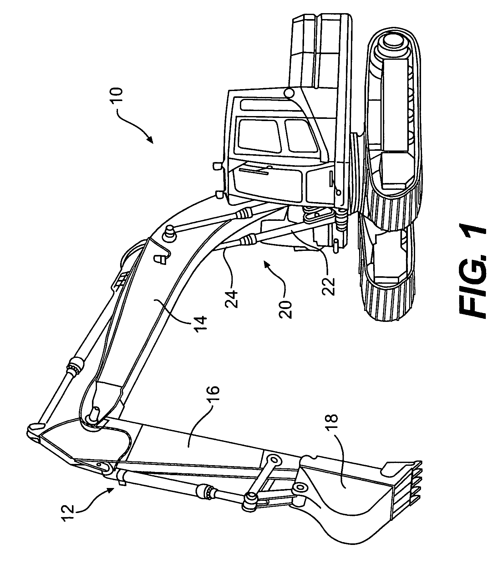
[0011]FIG. 1 shows an exemplary work machine 10. Work machine 10 may include, for example, an excavator, loader, or any machine having a hydraulically powered work implement 12. In one embodiment, implement 12 may include a boom 14, a stick 16, and a bucket 18. Operations performed by implement 12 may include, for example, lifting, lowering, and otherwise moving a load (not shown).

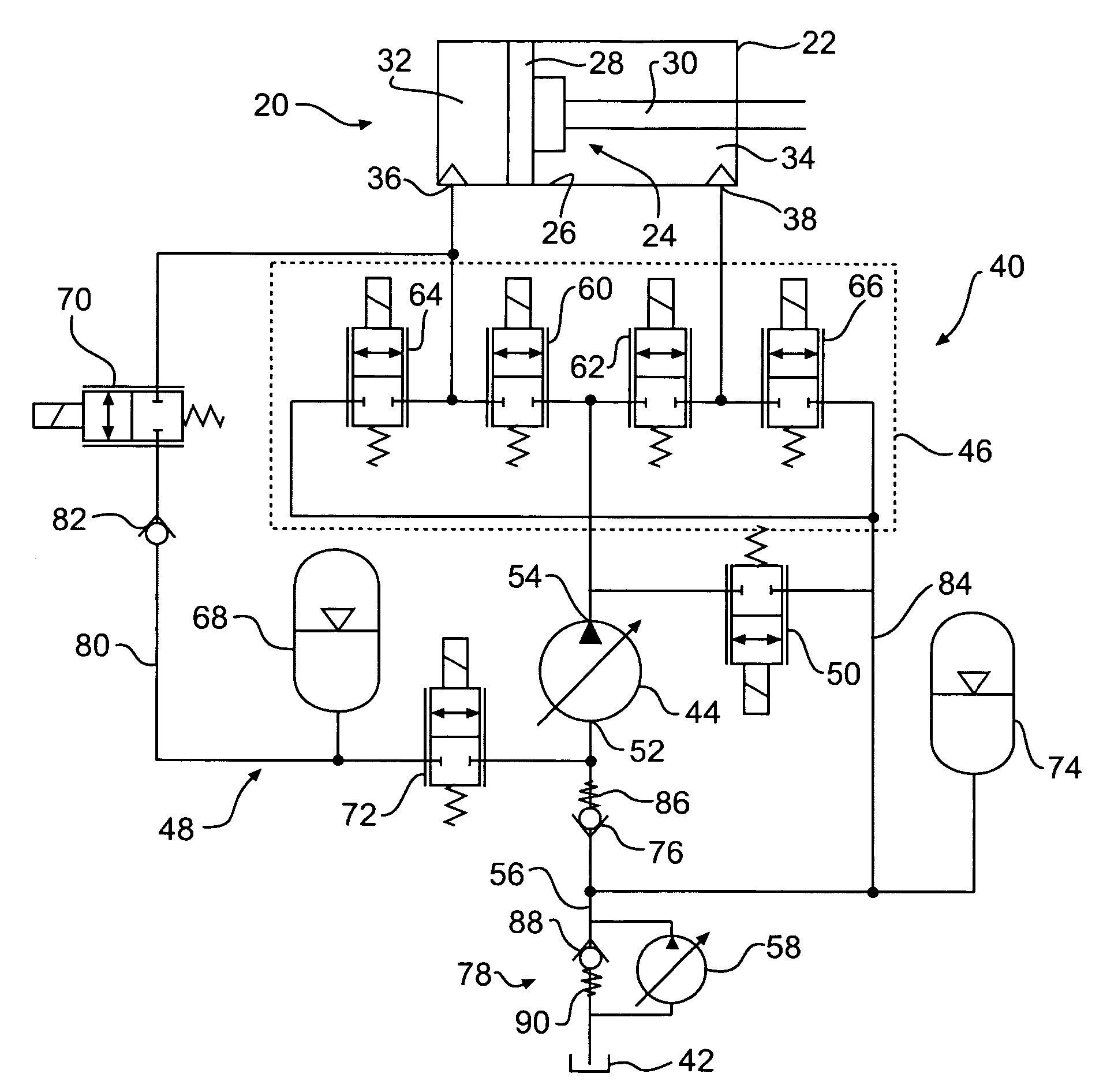
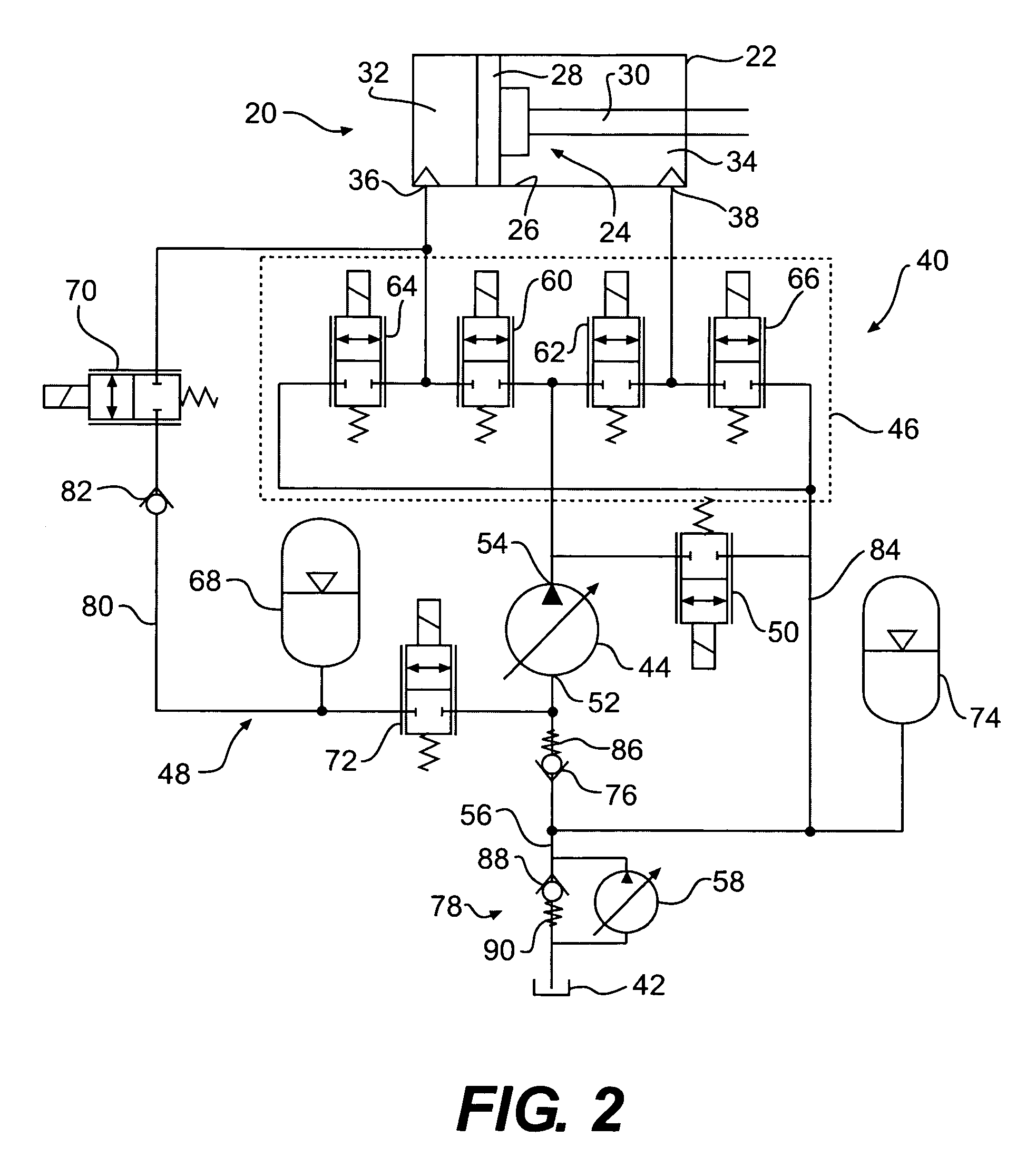
[0012]Implement 12 may be moved to perform its various functions by one or more hydraulic actuators 20. Hydraulic actuator 20 may include any device configured to receive pressurized hydraulic fluid and convert it into a mechanical force and motion. For example, hydraulic actuator 20 may include a fluid motor or hydrostatic drive train. Additionally or alternatively, hydraulic actuator 20 may include a double acting hydraulic cylinder embodied by a housing 22 and a piston 24. Elements of hydraulic actuator 20, one known in the art, may be seen in greater detail in FIG. 2.

[0013]Housing 22 may include a vess...


PUM


Abstract

A hydraulic system may include a hydraulic actuator. The hydraulic system may also include a pump having a pump inlet and a pump outlet, and the pump may be configured to supply fluid to the hydraulic actuator. The hydraulic system may further include an energy recovery system operatively connected between the hydraulic actuator and the pump. The energy recovery system may be configured to store fluid from the hydraulic actuator under an overrunning load condition, and the stored fluid may be directed through the pump inlet and into the hydraulic actuator.

Description

TECHNICAL FIELD[0001]The present disclosure relates to energy recovery, and more particularly to a system and method for recovering potential energy of a linkage system using a hydraulic circuit.BACKGROUND[0002]A work machine may be used to move heavy loads, such as earth, construction material, and / or debris, and may include, for example, a wheel loader, an excavator, a front shovel, a bulldozer, a backhoe, and a telehandler. The work machine may utilize a work implement to move the heavy loads. The work implement of the work machine may be powered by a hydraulic system that may use pressurized fluid to actuate a hydraulic actuator to move the work implement.[0003]During operation of the work machine, the implement may be raised to an elevated position. As the implement may be relatively heavy, the implement may gain potential energy when raised to the elevated position. As the implement is released from the elevated position, this potential energy may be converted to heat when pre...

Claims


Application Information

Patent Timeline
Patent Type & Authority Patents(United States)
IPC IPC(8): F16D31/02
CPCE02F9/2217F15B21/14F15B11/024F15B2211/88F15B2211/20546F15B2211/20576F15B2211/30505F15B2211/30575F15B2211/3111F15B2211/3144F15B2211/31582F15B2211/327F15B2211/35F15B2211/40515F15B2211/413F15B2211/41581F15B2211/426F15B2211/45F15B2211/46F15B2211/55F15B2211/625
Inventor ZHANG, JIAOMA, PENGFEISCHWAB, MICHAELPATEL, KALPESH N.SHANG, TONGLIN
Owner CATEPILLAR SARL
Why Eureka
Try Eureka