Recirculating exhaust system

a technology of exhaust system and hood, which is applied in ventilation systems, ventilation processes, and domestic stoves or ranges. it can solve the problems of hoods, hoods, and system energy loss, and achieve the effect of reducing the net energy loss of exhaust systems

Active Publication Date: 2009-10-22
HALTON GROUP LTD
View PDF140 Cites 78 Cited by
  • Summary
  • Abstract
  • Description
  • Claims
  • Application Information

AI Technical Summary

Benefits of technology

[0008]The embodiments variously provide features that help to reduce net energy loss in exhaust systems and / or provide for energy recovery.

Problems solved by technology

Exhaust systems are responsible for a significant loss of energy from industrial and commercial production facilities such as manufacturing facilities, commercial kitchens, laboratories, etc.
One of the losses caused by exhaust systems is a result of the withdrawal of significant amounts of conditioned air from the space where contaminants are being produced, which conditioned air must be replaced by conditioning replacement air.
Another loss is the energy required to operated exhaust system itself.
Examples of such systems are provided by U.S. Pat. No. 4,143,645 for “Self-contained exhaust hood with heat exchanger and method of exhausting air,” U.S. Pat. No. 6,347,626 for “Ventilation system for a kitchen,” U.S. Pat. No. 4,483,316 for “Air ventilation system.” and U.S. Pat. No. 4,483,316 for “Air ventilation system.” These systems, however, because the movement of air is inherently turbulent below the hood and around it, vigorous mixing occurs and hoods.
As a result, contaminants enter the conditioned air, often more vigorously because of the turbulence generated by the make-up air discharge, and thus, the exhaust hoods are largely required to exhaust as much conditioned air as in systems where make-up air is introduced remote from the hood.
In addition to the loss of conditioned air, and the concomitant need to replace the exhausted air by conditioning replacement air, exhaust system may inherently lose energy or materials that would have commercial value if they could be recovered and used.
Because of the dilution of the exhaust stream with conditioned air from the hood environment, however, the concentrations and temperatures are such that energy or material recovery is made difficult.
In addition, fouling caused by effluent streams is a performance and maintenance problem for energy recovery systems.
For example, heat transfer coefficients of surfaces drop quickly as a result of fouling.
Another issue in the design of exhaust systems is the typical permanence of the configuration once exhaust and utility connections are laid out and installed in a structure.
Short circuit exhaust systems offer greater flexibility than those which are connected to outside vents, but utility connections can still pose problems and sometimes short circuit operation is undesirable or impractical in certain facilities.

Method used


Image

  • Recirculating exhaust system
  • Recirculating exhaust system
  • Recirculating exhaust system

Examples


Embodiment Construction

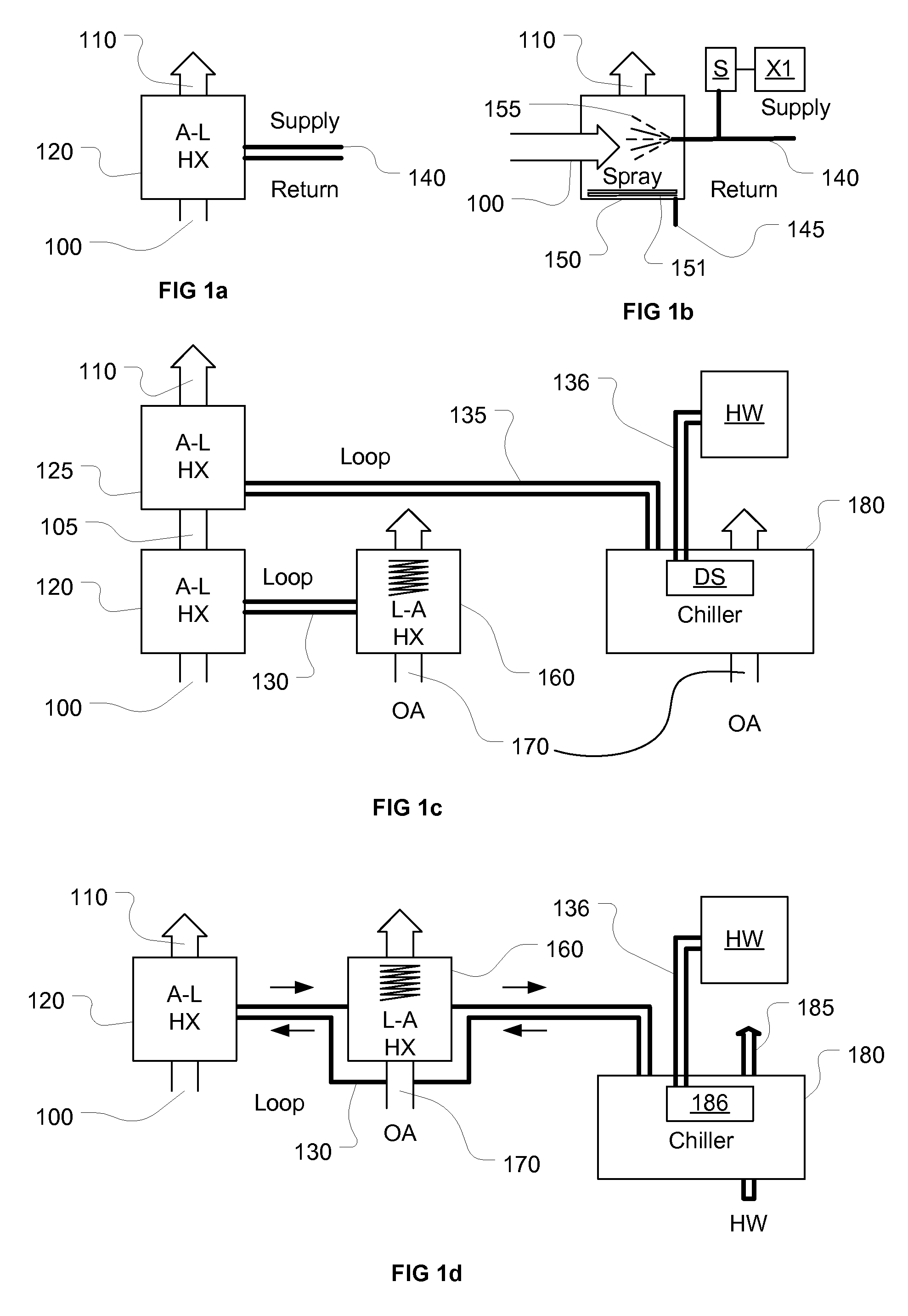
[0074]In addition to the fouling problem, there is an opportunity cost and a disposal problem associated with the collection of “waste” heat. The heat collected from the heat exchanger can simply be discarded, for example, by sending consumed cooling water into a sewer or transferring heat from a coolant to ambient outdoor air using a liquid-air heat exchanger, or by transferring heat to other heat sinks, such as the earth, natural water bodies, cooling towers, etc. The opportunity associated with this disposal problem includes the re-use of the otherwise wasted materials and enthalpy, for example, grease, which can provide a source for biofuels, and heat. Another opportunity is that cleaning exhaust rather than simply sending into the environment, provides environmental benefits.

[0075]One group of applications that motivate the embodiments in the instant specification are those where permanent connection to an exhaust system is either undesirable or impossible. These are so-called ...


PUM


Abstract

Systems, devices and methods provide energy recover, modular systems to build and revise commercial kitchen services, closed circuit exhaust, and high efficiency capture and containment of fumes from cooking processes.

Description

CROSS-REFERENCE TO RELATED APPLICATIONS[0001]This patent applications claims the benefit of priority to U.S. Provisional Application No. 60 / 745,093 for “RECIRCULATING EXHAUST SYSTEM,” filed 18 Apr. 2007 and U.S. Provisional Application No. 60 / 745,276 for “RECIRCULATING EXHAUST SYSTEM,” filed 20 Apr. 2007, which have been incorporated by reference in its entirety.BACKGROUND OF THE INVENTION[0002]Exhaust systems are responsible for a significant loss of energy from industrial and commercial production facilities such as manufacturing facilities, commercial kitchens, laboratories, etc. One of the losses caused by exhaust systems is a result of the withdrawal of significant amounts of conditioned air from the space where contaminants are being produced, which conditioned air must be replaced by conditioning replacement air. Another loss is the energy required to operated exhaust system itself.[0003]As a result of the recognition of a need to minimize the loss of conditioned air through ...

Claims


Application Information

Patent Timeline
Patent Type & Authority Applications(United States)
IPC IPC(8): B08B17/00F28D15/00F24C15/20F24C15/18
CPCB08B15/023F24C15/2042F24C15/2057F28C3/06Y02B30/52F28D21/0003F28F1/24F28F1/34F28D15/00A61L9/20B01D53/72B01D53/76B01D2257/7022B01D2258/0275B01D2259/804A61L2/10A61L9/014A61L2209/14A61L2209/16A61L2209/212F24C15/20Y02B30/56B01D53/007B08B15/00
Inventor LIVCHAK, ANDREY V.SCHROCK, DEREK W.SIPILA, OLLIMEREDITH, PHILIP J.BEARDSLEE, DARRIN WBAGWELL, RICK A.FALLER, ANDREW C.
Owner HALTON GROUP LTD
Why Eureka
Try Eureka