
Energy recovery system and method using an organic rankine cycle with condenser pressure regulation

a technology of condenser pressure regulation and energy recovery system, which is applied in the direction of engine cooling apparatus, steam engine plants, liquid cooling, etc., can solve the problem of low thermal efficiency of internal combustion engines

Active Publication Date: 2011-03-03
CUMMINS INTPROP INC
View PDF99 Cites 79 Cited by
  • Summary
  • Abstract
  • Description
  • Claims
  • Application Information

AI Technical Summary

Benefits of technology

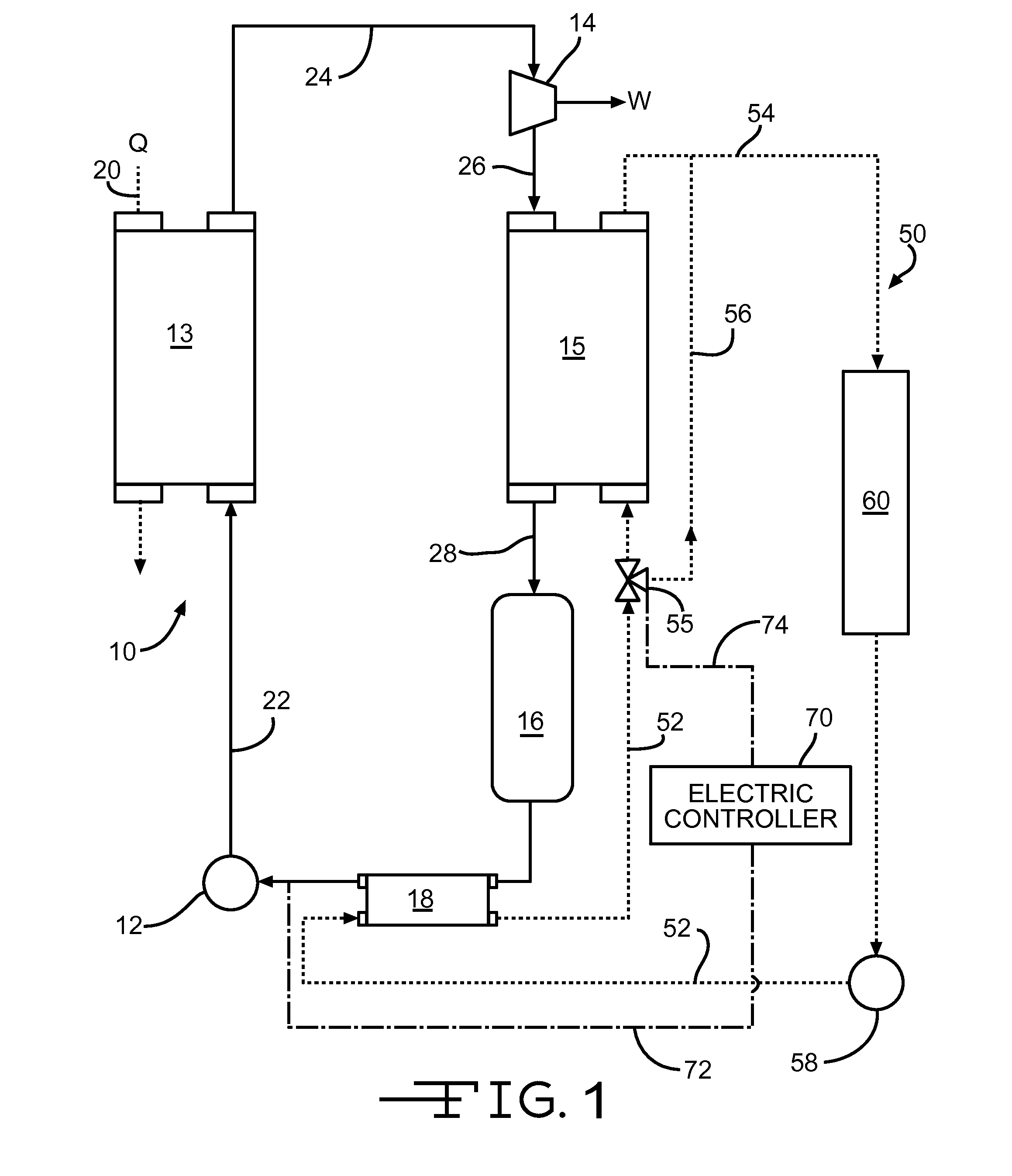
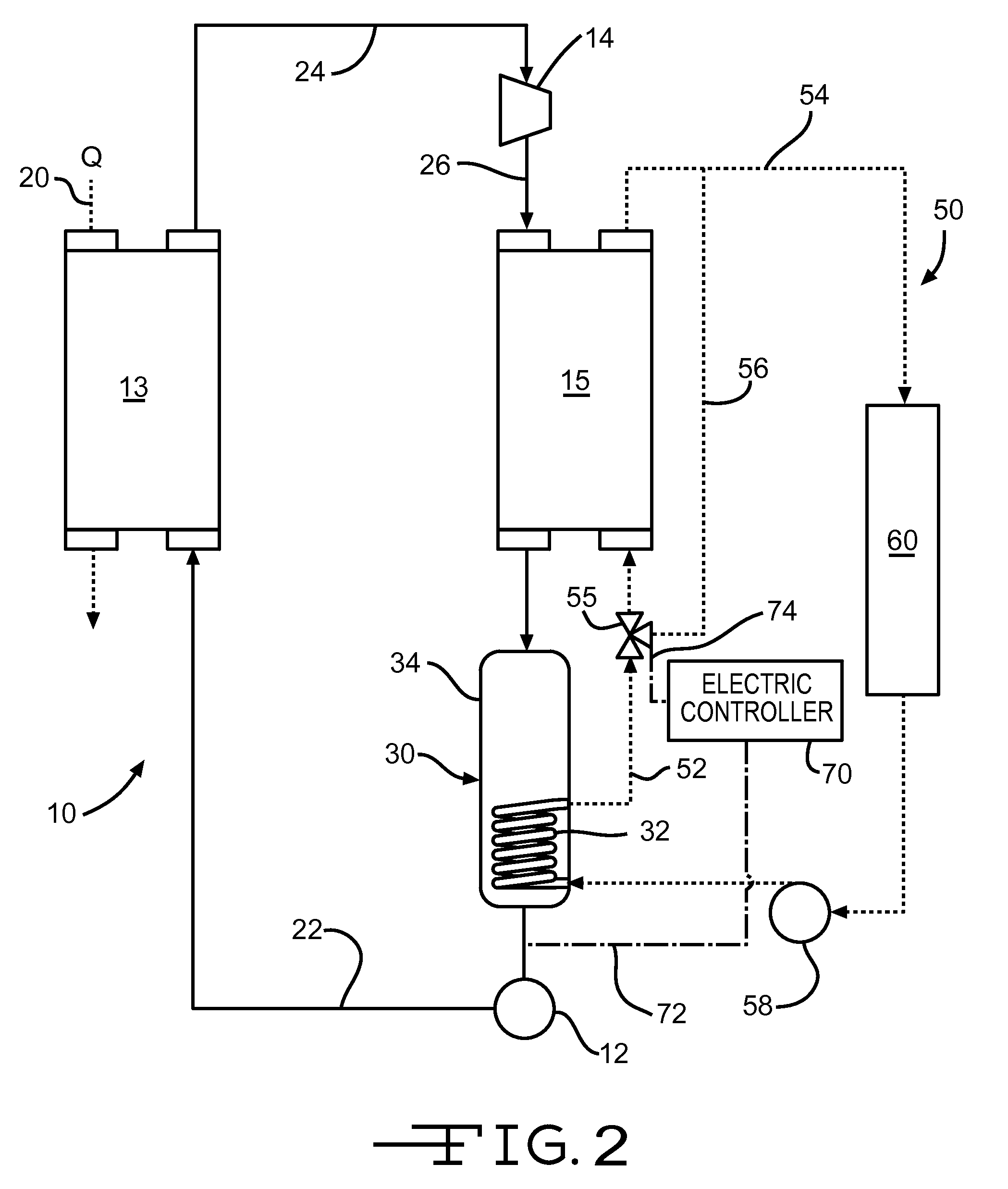
[0005]The system and method may further include selectively varying the bypassed coolant flow based on at least one of a temperature and a pressure of the organic fluid upstream of the fluid pump, and further may be based on a saturation pressure of the organic fluid near an inlet of the fluid pump. A subcooler may be positioned within the receiver so as to be immersed in the organic fluid accumulated in the receiver. A subcooler may be provided downstream of the receiver and upstream of the fluid pump. A bypass valve may be positioned upstream of the condenser along a coolant flow circuit to selectively bypass coolant f

Problems solved by technology

It is well known that the thermal efficiency of an internal combustion engine is very low.

Method used


Image

  • Energy recovery system and method using an organic rankine cycle with condenser pressure regulation
  • Energy recovery system and method using an organic rankine cycle with condenser pressure regulation
  • Energy recovery system and method using an organic rankine cycle with condenser pressure regulation

Examples


Embodiment Construction

[0010]Applicants have recognized that during large transient heat inputs from the waste heat or abrupt changes in the temperature of the coolant flowing through the condenser, a rapid condenser pressure decrease may occur causing the fluid in the receiver to boil. As a result, the circulation pump, in the ORC, may undesirably experience cavitation. Applicant has recognized that measures can be taken to assure that sufficient fluid pressure is maintained thereby preventing pump cavitation.

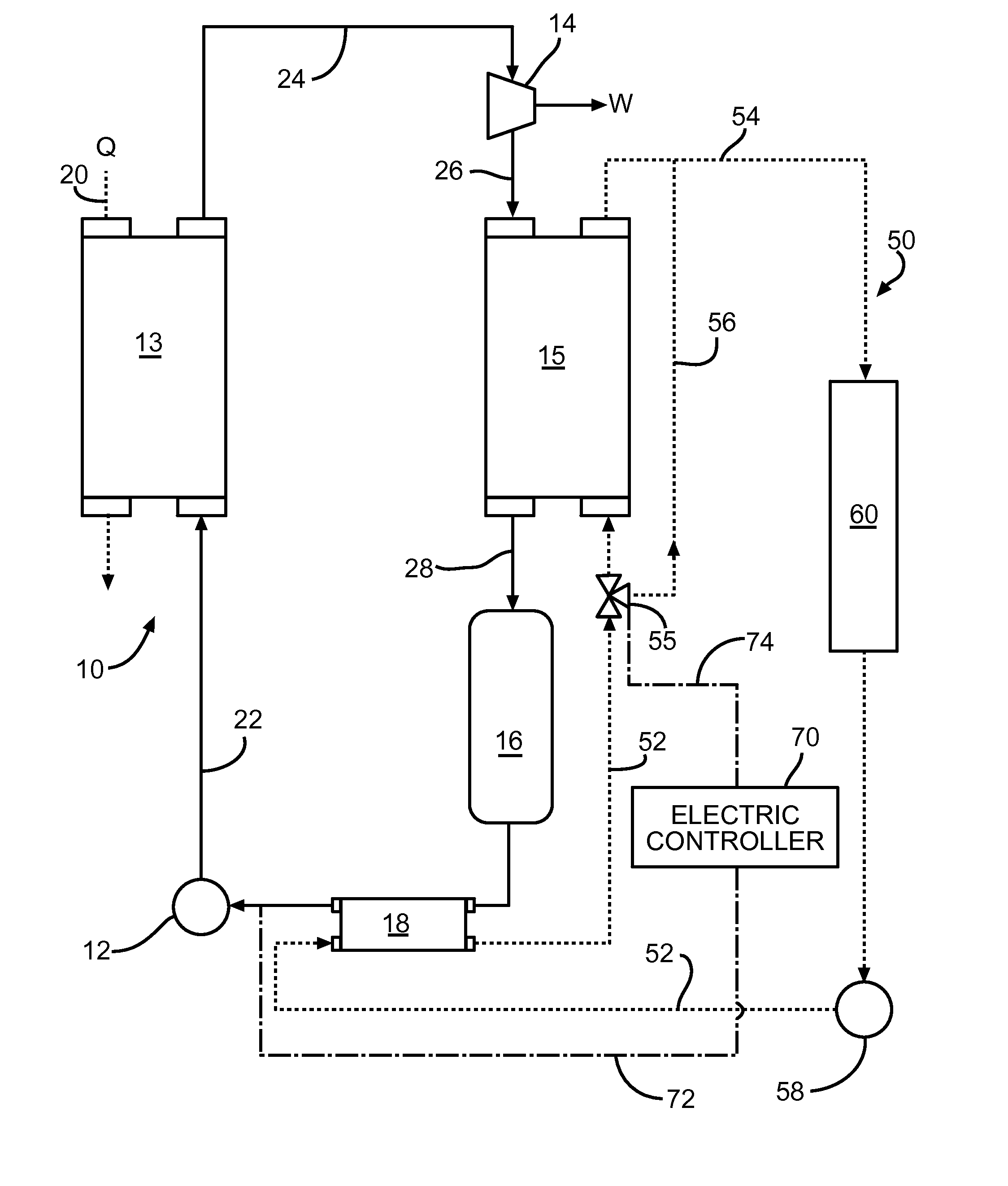
[0011]In particular, FIG. 1 presents a schematic of a closed loop Organic Rankine Cycle (ORC) system 10 in accordance with an exemplary embodiment of the present invention which addresses the aforementioned issue. The ORC system 10 includes a circulating pump 12 for circulating a liquid phase organic fluid, such as R-245fa, or any other suitable refrigerant, through an organic fluid circuit including conduits 22, 24, 26, and 28. A heat exchanger or boiler 13, positioned downstream of pump 12, receiv...


PUM


Abstract

An energy recovery system and method using an organic rankine cycle is provided for recovering waste heat from an internal combustion engine, which effectively controls condenser pressure to prevent unwanted cavitation within the fluid circulation pump. A coolant system may be provided with a bypass conduit around the condenser and a bypass valve selectively and variably controlling the flow of coolant to the condenser and the bypass. A subcooler may be provided integral with the receiver for immersion in the accumulated fluid or downstream of the receiver to effectively subcool the fluid near the inlet to the fluid pump.

Description

FIELD OF THE INVENTION[0001]The present invention generally relates to energy recovery from the waste heat of a prime mover machine such as an internal combustion engine.BACKGROUND OF THE INVENTION[0002]It is well known that the thermal efficiency of an internal combustion engine is very low. The energy not extracted as usable mechanical energy is typically expelled as waste heat into the atmosphere by way of the engine's exhaust gas emission, charge air cooling and engine coolant heat rejection.[0003]It is known to employ a relatively simple, closed-loop Organic Rankine Cycle (ORC) system to recapture the engine's waste heat otherwise lost to the surrounding ambient. Such a system typically comprises a circulating pump, pumping a liquid phase organic, working fluid through a boiler wherein the working fluid undergoes a phase change from a liquid to a pressurized, gaseous phase. The boiler receives its heat input from the engine's waste heat streams. The gaseous phase working fluid ...

Claims


Application Information

Patent Timeline
IPC IPC(8): F01K25/00
CPCF01K9/003F01K13/02F01K23/065F01P3/2207F01K25/10
Inventor ERNST, TIMOTHY C.NELSON, CHRISTOPHER R.ZIGAN, JAMES A.
Owner CUMMINS INTPROP INC
Learn More