
Vehicle suspension with improved radius arm to axle attachment

a technology of radius arm and axle attachment, which is applied in the direction of suspension arms, resilient suspensions, vehicle components, etc., can solve the problems of increasing the cost and part count of suspension systems, affecting the design of suspension systems, and requiring a greater number of expensive bushings for four and five link systems

Active Publication Date: 2007-09-18
FORD GLOBAL TECH LLC
View PDF14 Cites 17 Cited by
  • Summary
  • Abstract
  • Description
  • Claims
  • Application Information

AI Technical Summary

Benefits of technology

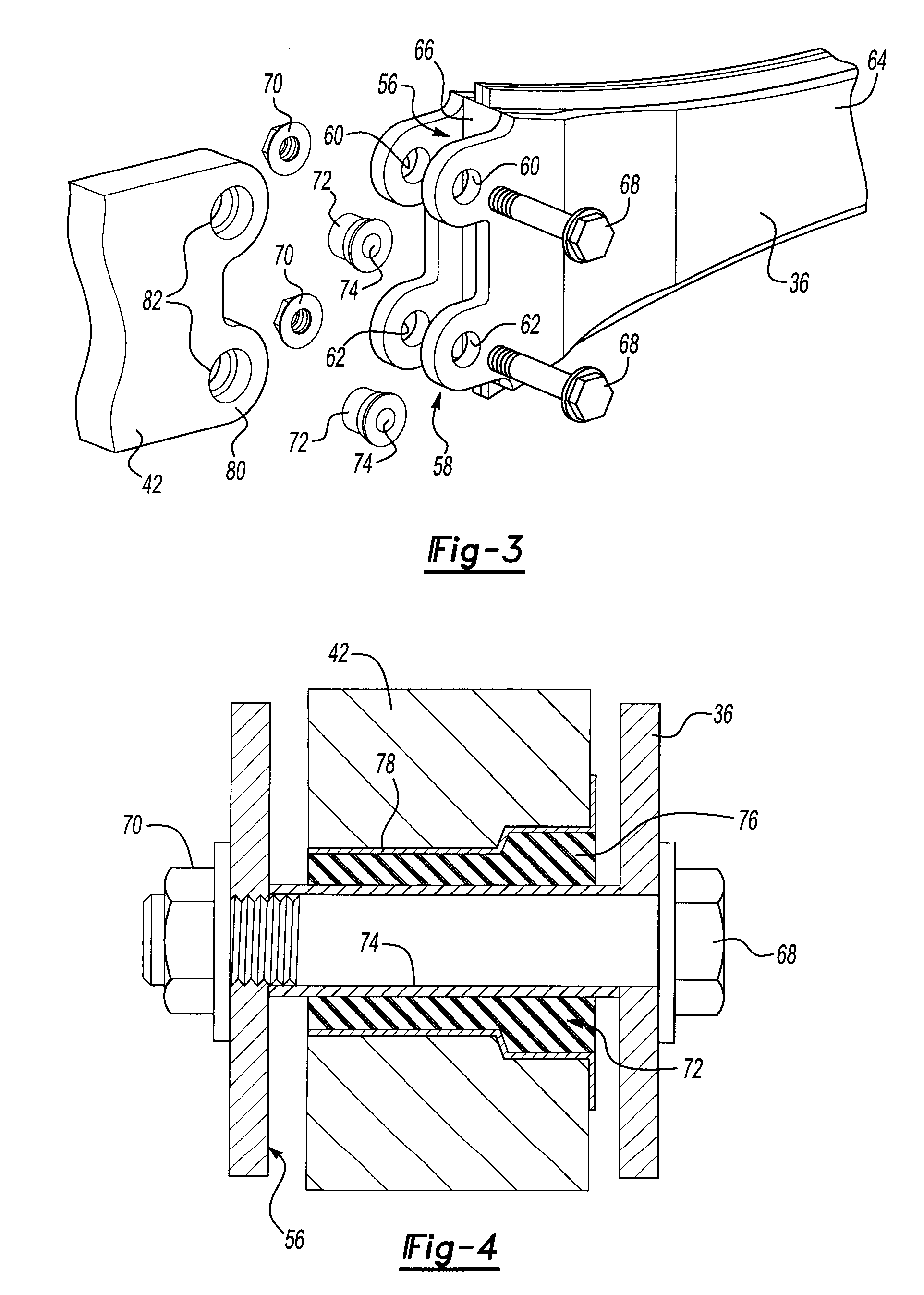
The present invention provides a vehicle suspension system subassembly that supports a vehicle on an axle. The subassembly includes right and left radius arms, each with a bracket for connecting to the axle. A track bar extends laterally from the axle to the frame of the vehicle. The invention also provides an improved radius arm with a hollow elongated arm formed as a two-part clamshell structure fabricated as sheet metal half shells that are welded together. The radius arm is connected to the axle through a connection structure that includes a bracket and fasteners. The invention also includes a combination of an axle and radius arm with the radius arm connected to the axle through fasteners that are oriented parallel to the central axis of the axle. The bushings are connected to the axle connector and the frame connector bushing in a quadrilateral array on one side of the axle. These features and aspects of the invention improve the stability and performance of the vehicle suspension system.

Problems solved by technology

However, these systems have pairs of upper and lower arms that increase the cost and part count of the suspension systems.
In addition, four and five link systems generally require a greater number of expensive bushings.
Any portion of the radius arms that extend beyond the axle to the opposite side may complicate suspension system design and create interference with the steering linkage.
Longer radius arms also tend to reduce the caster angle sensitivity relative to suspension deflection and ride height.

Method used


Image

  • Vehicle suspension with improved radius arm to axle attachment
  • Vehicle suspension with improved radius arm to axle attachment
  • Vehicle suspension with improved radius arm to axle attachment

Examples


Embodiment Construction

)

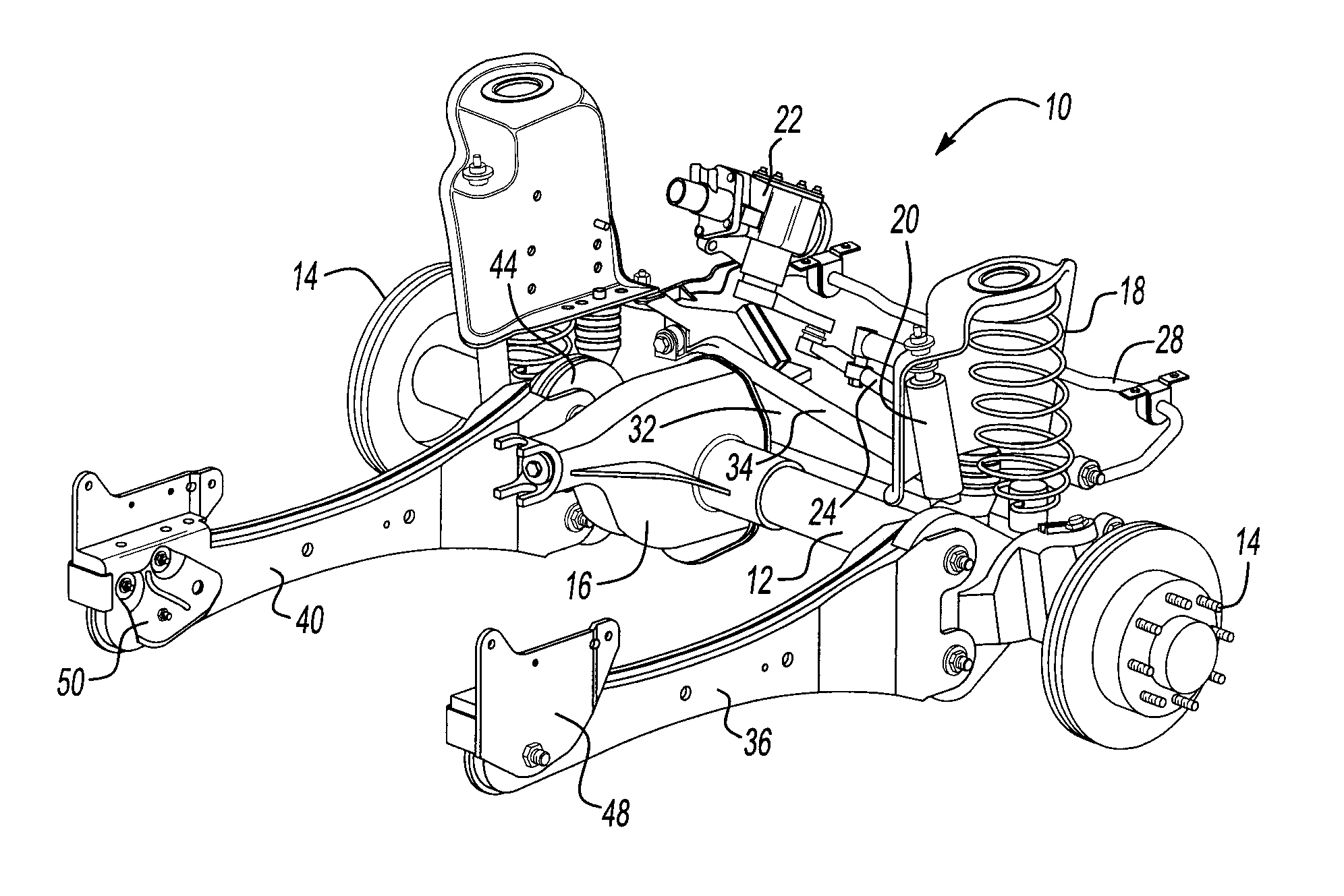
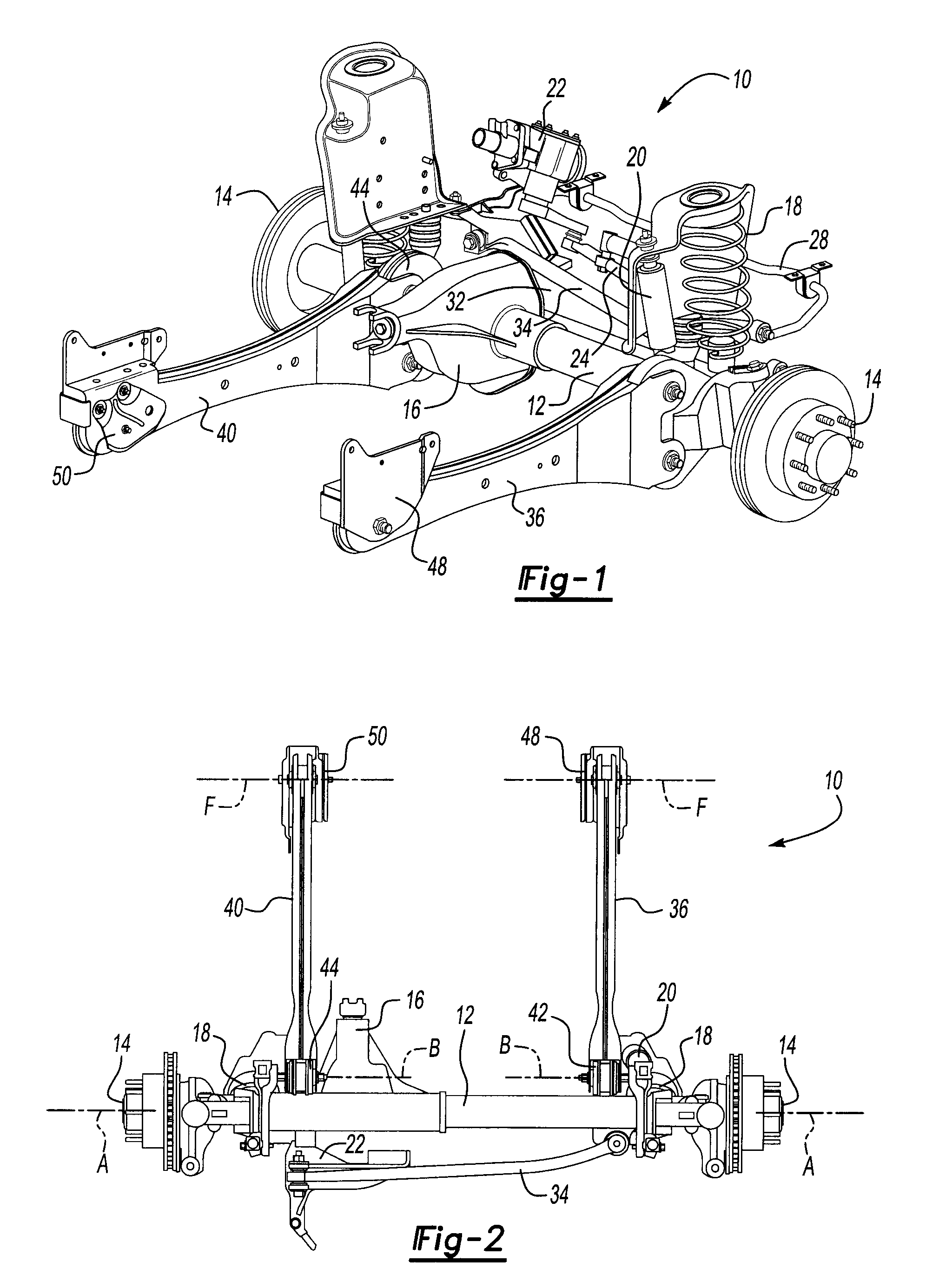
[0026]Referring to FIGS. 1 and 2, a front axle suspension assembly 10 is shown to include a front axle tube 12 that extends between the front wheel mounts 14. It should be understood that the front axle suspension assembly 10 is described as being exemplary and it should not be understood to limit the construction of the claims of this application to front axles since the invention is equally applicable with a reversed fore-and-aft orientation to rear axle suspension assemblies. The suspension assembly 10 also includes a ring / pinion housing 16 to which a drive shaft (not shown) of a four wheel drive vehicle may be connected. The suspension assembly 10 also includes a set of springs 18 and shock absorbers 20 that are used to provide suspension damping, as is well known in the art. A steering gear 22 is shown above the front axle suspension assembly 10 that functions to steer the front wheels (not shown). A drag link 24, and stabilizer bar 28 are also provided forward of the front ax...


PUM


Abstract

A vehicle suspension system having radius arms that are connected to axle brackets through vertically arranged bushings. A third link of the suspension system is a track bar that connects one end of the axle to a laterally spaced point on the frame of the vehicle. The radius arms are sheet metal fabricated members that are assembled in a clam shell arrangement.

Description

BACKGROUND OF THE INVENTION[0001]1. Field of the Invention[0002]The present invention relates to the structure of a three link vehicle suspension system including a pair of radius arms and a track bar.[0003]2. Background Art[0004]Vehicle suspension systems connect an axle to a frame of a vehicle. Suspension system components typically include shock absorbers, springs, torsion bars, and other components. Vehicle suspensions are dynamic systems that move in response to braking, turning, acceleration and road induced impacts. The vehicle must be designed to allow for substantial movement of suspension system components relative to each other and to the other vehicle components.[0005]Four and five link suspension systems have been developed that offer some advantages in regard to vehicle design. However, these systems have pairs of upper and lower arms that increase the cost and part count of the suspension systems. In addition, four and five link systems generally require a greater num...

Claims


Application Information

Patent Timeline
Patent Type & Authority Patents(United States)
IPC IPC(8): B60G1/04
CPCB60G7/001B60G9/00B60G11/50B60G2200/314B60G2200/341B60G2204/1482B60G2204/41B60G2206/11
Inventor LONGWORTH, PAULHESS, HARRYSTANLEY, JOHN
Owner FORD GLOBAL TECH LLC
Learn More