Indicator lighting device

a technology for lighting devices and indicators, which is applied to instrumentation, planar/plate-like light guides, and indication elements. it can solve the problems of uneven illumination, difficult to keep the level of light taken into the light introduction portion constant, and limited improvement of indicator luminan

Inactive Publication Date: 2007-09-18
NIPPON SEIKI CO LTD
View PDF11 Cites 14 Cited by
  • Summary
  • Abstract
  • Description
  • Claims
  • Application Information

AI Technical Summary

Benefits of technology

[0012]Moreover, the invention is characterized in that a display panel is disposed behind the indicator, the light introduction portion is positioned at the front of the display panel together with the indication portion, and the periphery of them is covered with a cover having a light shielding effect.

Problems solved by technology

Therefore, there has been a problem in usability of the light from the light sources, and improvement in luminance of the indicator has been limited.
Moreover, there has been an issue that in view of circumstances that the light introduction portion moves on the fronts of respective light sources as point light sources, a level of light taken into the light introduction portion is hard to be kept constant, and unevenness in illumination tends to occur.

Method used


Image

  • Indicator lighting device
  • Indicator lighting device
  • Indicator lighting device

Examples


second embodiment

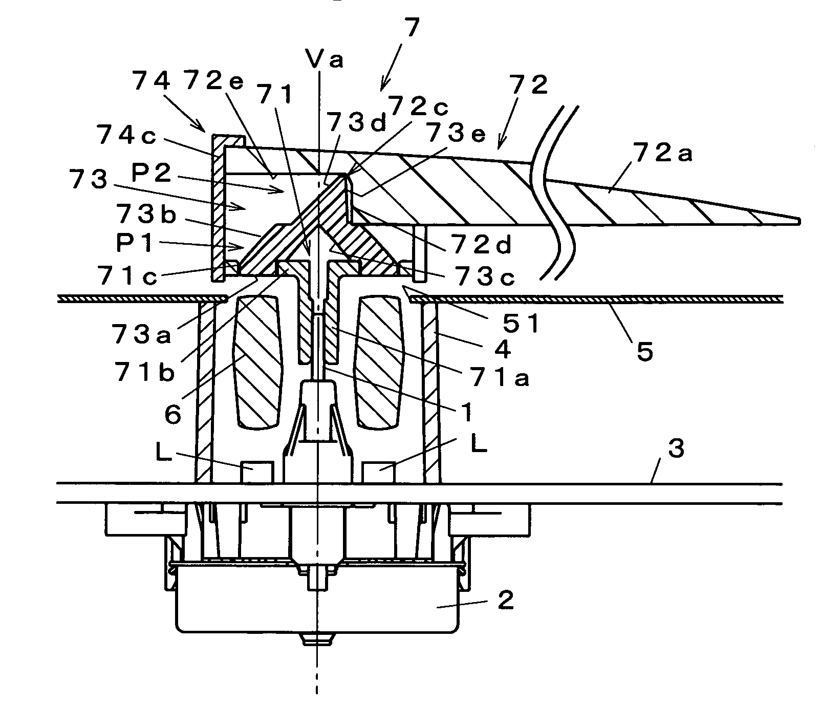
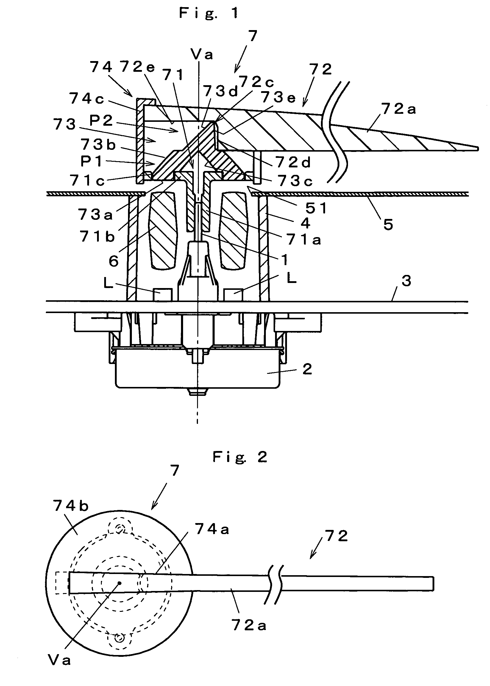
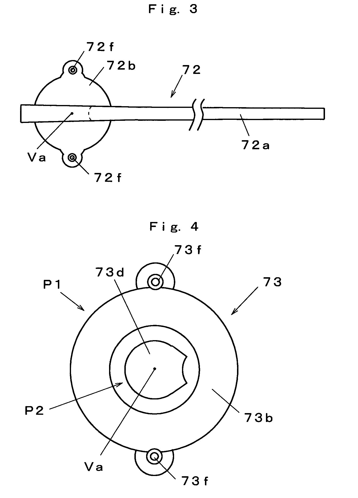
[0053]FIG. 7 is a front view showing the major portion of the invention. In the embodiment, the light introduction member 73 and the indication member 72 are not separate components, and they are formed from a single component having a light introduction portion 73 and an indication portion 72. The light introduction portion 73 has a first part (part) P1 having a reverse-W-shaped section that is line-symmetric with a rotation axis Va as a reference, a first reflective surface 73b is formed on an outer wall face of the first part P1 while a second reflective surface 73c is formed on an inner wall face of it, and a third reflective surface 73d is positioned at a second part P2 that is a rear side of the first and second reflective surfaces 73b, 73c.

[0054]Light from light sources L1 is introduced into the indicator portion 72 along a channel from a light receiving portion 73a to the indicator portion 72 through the first reflective surface 73b, second reflective surface 73c, and third...

third embodiment

[0056]FIG. 8 is a front view showing the major portion of the invention. In the embodiment, a third part P3 extending along a rotation axis Va is formed between a second part P2 and an indication portion 72, a fourth reflective surface 731 facing the third reflective surface 73d and a fifth reflective surface 732 facing the fourth reflective surface 731 are provided on the third part P3, and light from the third reflective surface 73d is supplied to the indication portion 72 via the fourth and fifth reflective surface 731, 732. In this case, the indication portion 72 is formed as a separate component from the third part P3, and disposed on the first part P1.

first embodiment

[0057]According to such an embodiment, similar effects as in the first embodiment can be expected, and in addition, an effective configuration is given when the indication portion 72 extends so as to cross a bottom wall portion of an indicator cover 74.

INDUSTRIAL APPLICABILITY

[0058]The invention can be applied to indicator lighting devices of various mobile bodies typically including motorcycles, ships, agricultural construction machines, and aircrafts, in addition to vehicles.


PUM


Abstract

An indicator lighting device in which light introduction efficiency into a indication portion can be improved, brightness is good and unevenness in lighting is small is provided; wherein an indicator 7 which has a translucent indication member (indication portion) 72 and a light introduction member (light introduction portion) 73 and is operated around an axis by a drive shaft 1 of a drive unit 2, light sources L which are disposed around the drive shaft 1 and illuminate the indication member 72 through the light introduction member 73 are provided, and the light introduction member 73 has a light receiving surface 73a for receiving light from the light sources L, a first reflective surface 73b for focusing light introduced from the light receiving surface 73a to a position of a rotation axis Va of the drive shaft 1, a second reflective surface 73c which is formed between the first reflective surface 73b and the rotation axis and reflects light from the first reflective surface 73b in a direction along the rotation axis Va, and a third reflective surface 73d which is formed on the rotation axis Va in a way of facing the second reflective surface 73c and reflects light from the second reflective surface 73c in a longitudinal direction of the indication member 72.

Description

[0001]This application is a U.S. national phase application of PCT international application PCT / IB2004 / 015327, filed on Oct. 8, 2004, which in turn claims the benefit of Japanese Application No. 2003-354095, filed Oct. 14, 2003, the disclosures of which Applications are incorporated by reference herein.TECHNICAL FIELD [0002]The present invention relates to an indicator lighting device, which is applied to, for example, indicator instruments of vehicles, for lighting an indicator operated by a drive shaft of a predetermined drive unit.BACKGROUND ART [0003]As an indicator lighting device of this type, a device described in JP-A-8-043145 has been known. The indicator lighting device described in that literature has an indicator which comprises a translucent material and is operated around an axis with a drive shaft, and a plurality of light sources for illuminating the indicator, wherein the indicator has a light introduction portion for introducing light from the light sources formed...

Claims


Application Information

Patent Timeline
Patent Type & Authority Patents(United States)
IPC IPC(8): G01D11/28F21V8/00G01D13/22G01D13/26G01D13/28G12B11/04
CPCG01D11/28G01D13/265G01D13/28G02B6/0018G02B6/0028G12B11/04B60K2370/6992B60K35/00
Inventor OBATA, MASATOSHOJI, NAOJI
Owner NIPPON SEIKI CO LTD
Why Eureka
Try Eureka