Dental tray for obtaining dental impression of edentulous patient

a dental impression and edentulous patient technology, applied in the field of new dental impression tray, can solve the problems of unpleasant patient use of adhesives, discomfort and sometimes gagging, new problems or not working well with today's wide range of impression materials, etc., and achieve the effect of less discomfort, accurate impression and accurate impression

Active Publication Date: 2007-09-25
GLOBAL DENTAL IMPRESSION TRAYS
View PDF14 Cites 19 Cited by
  • Summary
  • Abstract
  • Description
  • Claims
  • Application Information

AI Technical Summary

Benefits of technology

[0009]It is an object of this invention to provide a new dental tray for obtaining an accurate impression of the jaw and gingiva areas of the mouth of an edentulous patient where the dental tray has a predetermined shape that accommodates the anatomical shape of the edentulous patient's jaw and gingiva areas so that the patient's jaw and gingiva areas are not deformed or influenced by the dental tray and the impression material is retained by the dental tray, without the need for adhesives on the dental tray to help retain the impression material, during the impression procedure.
[0010]Another object of this invention is to provide a new dental tray for obtaining an impression of the jaw and gingiva areas of the mouth of an edentulous patient that can be used with the entire range of impression materials from extralight to very heavy in density and can be used with a combination of different density impression materials to obtain an accurate impression.
[0011]Yet another object of this invention is to provide a new dental tray for obtaining an impression of the jaw and gingiva areas of the mouth of an edentulous patient that provides a means to uniformly transfer pressure applied by the operator to the dental tray so that the combination of the dental tray and the impression material is correctly seated in the patient's mouth to obtain an accurate impression with less discomfort to the patient, while allowing the operator to maintain their hand, wrist and arm in an ergonomically correct and comfortable position during the impression procedure.
[0012]To meet the objectives of the invention, the new dental tray comprises a body, at least two finger rest beams and a handle. The body having a body front end and a body rear end. The handle is attached to the body front end of the body so that the handle can be used to insert and remove the dental tray from the patient's mouth when the impression material is applied to the body of the dental tray and where the handle is narrow enough to allow the operator to negotiate placement of the dental tray without trapping open their fingers. Each of the finger rest beams are received longitudinally along the bottom side of the body and are specifically located on the body such that any pressure placed upon each of the finger rest beams will transfer along the length of each of the finger rest beams and into the body uniformly. The longitudinal length of each of the finger rest beams allow for different sized fingers of the operator to be accommodated anywhere along each of the finger rest beams. Each of the finger rest beams are connected to the handle, where the handle is also attached to the body, such that the combination of the body, handle and each of the finger rest beams form the dental tray.
[0013]The body comprises an upstanding outer wall portion, a channel portion and a central support portion having a predetermined shape that accommodates the anatomical shape of the edentulous patient's jaw and gingiva areas and a plurality of body openings. The shape of the body, being substantially close to the anatomy of the edentulous patient's jaw and gingiva areas, is designed to allow the body to retain a wide range of impression materials without directing the flow of the impression materials and without influencing or deforming the jaw and gingiva areas. The plurality of body openings further comprises a plurality of dumbbell shaped body openings and a plurality of circular shaped body openings. The plurality of dumbbell shaped body openings having a variety of sizes and orientations and the plurality of circular shaped body openings having a predetermined size. The dumbbell shaped body openings and the circular shaped body openings are positioned in the body at predetermined locations. This combination of openings cooperate to allow the impression material to vent through these openings with the least resistance to obtain the impression of the jaw and gingiva areas, while acting to retain the impression material until it is cured to prevent distortion of the impression material. In another embodiment of the invention, the body further comprises a thickened edge and a plurality of edge notches. The thickened edge being substantially circular in shape with a predetermined diameter and being received along the outer edge of the upstanding outer wall portion, the channel portion and the central support portion of the body to capture the anatomical features of the patient's mouth while the plurality of edge channels provide additional surface area to retain the layer of impression material on the thickened edge until it is cured to prevent distortion of the impression material. These features allow the body to successfully use a wide range of impression materials that vary from extralight to very heavy in density.

Problems solved by technology

The adhesive is odorous and distasteful, making the use of adhesives unpleasant for the patient.
While each of the different trays in the prior art do address certain problems with obtaining an accurate impression, they also create new problems or do not work well with today's wide range of impression materials.
One problem is that prior art causes excessive impression material to be expelled backward into the throat of the patient causing discomfort and sometimes gagging.
Another problem is that the prior art are not built to match the anatomy of an edentulous patient's jaw and gingiva areas.
This can lead to the dental tray deforming the patient's jaw and gingiva areas, thus preventing an accurate impression.
This also leads to having to use excessive impression material to obtain a reasonable impression, which contributes to a patient's discomfort and gagging.
Yet another problem is that the prior art does not work well with the entire range of impression materials that are now available from extralight to very heavy in density due to openings in the dental trays having either too small of openings or too large of openings.
Where the dental tray has small openings, the dental tray does not distribute the medium to very heavy density impression materials well.
Where the dental tray has large openings, the dental tray does not retain the extralight to medium density impression materials well.
Yet another problem is that the prior art does not provide a means for uniformly distributing pressure to the dental tray to seat the dental tray and impression material in the patent's mouth.
Since the prior art does not provide a way to distribute this pressure uniformly to the dental tray, often the dental tray will improperly seat deeper at the point where the pressure is applied and create an inaccurate impression.
Yet another problem is that the prior art does not provide a way to allow the operator to keep their hand, wrist and arm in an ergonomically correct position while placing the dental tray and impression material in the patient's mouth and while placing pressure on the dental tray to seat the dental tray and impression material.
At best, this can lead to the operator's fatigue, discomfort and loss of productivity; and, at worse, can lead to the operator becoming injured by having to repetitively place their hand, wrist and arm in awkward positions.

Method used


Image

  • Dental tray for obtaining dental impression of edentulous patient
  • Dental tray for obtaining dental impression of edentulous patient
  • Dental tray for obtaining dental impression of edentulous patient

Examples


Embodiment Construction

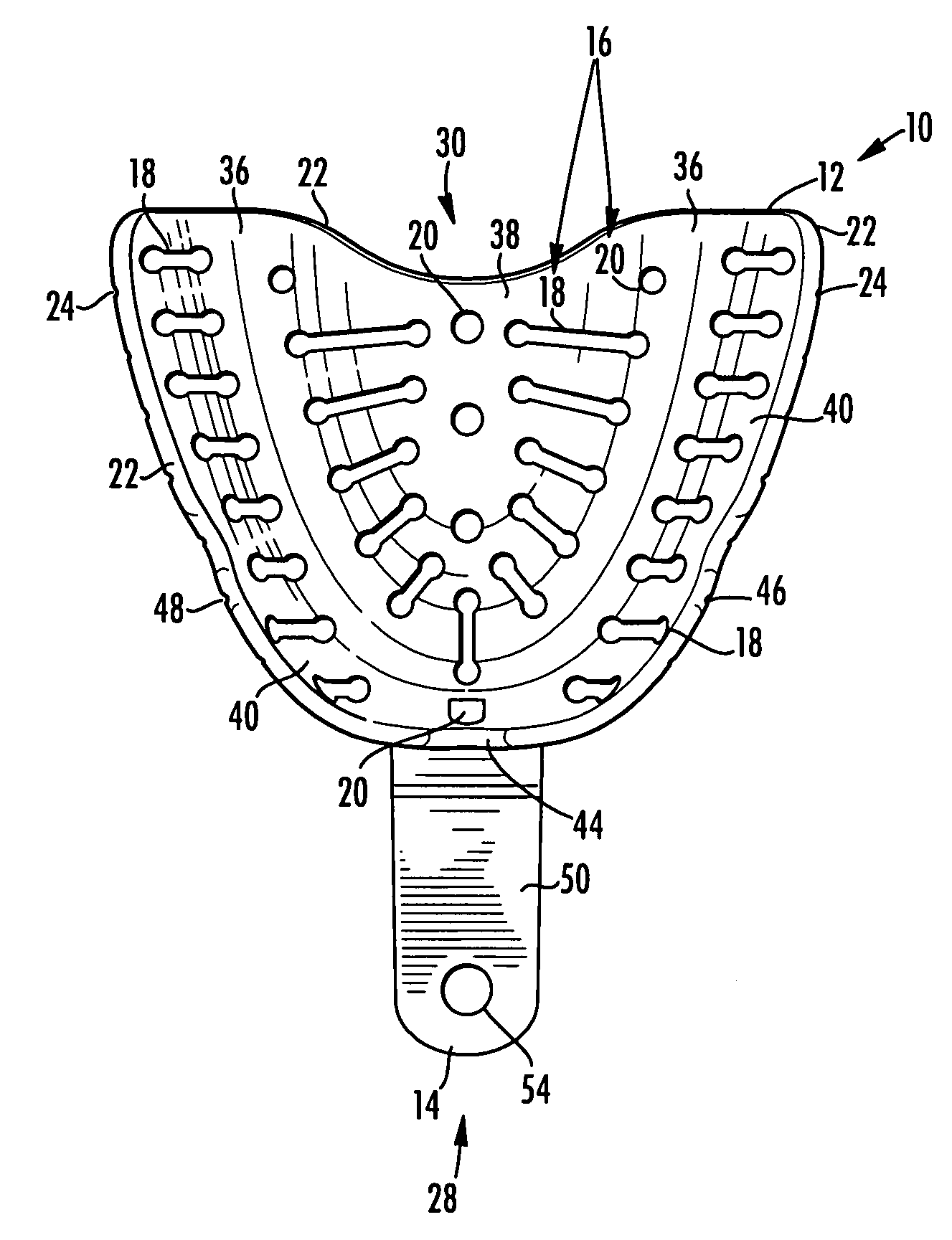
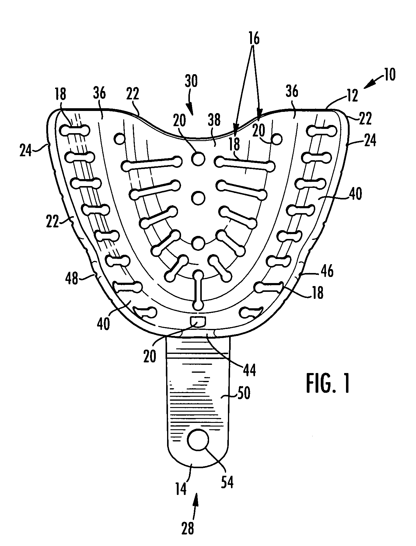
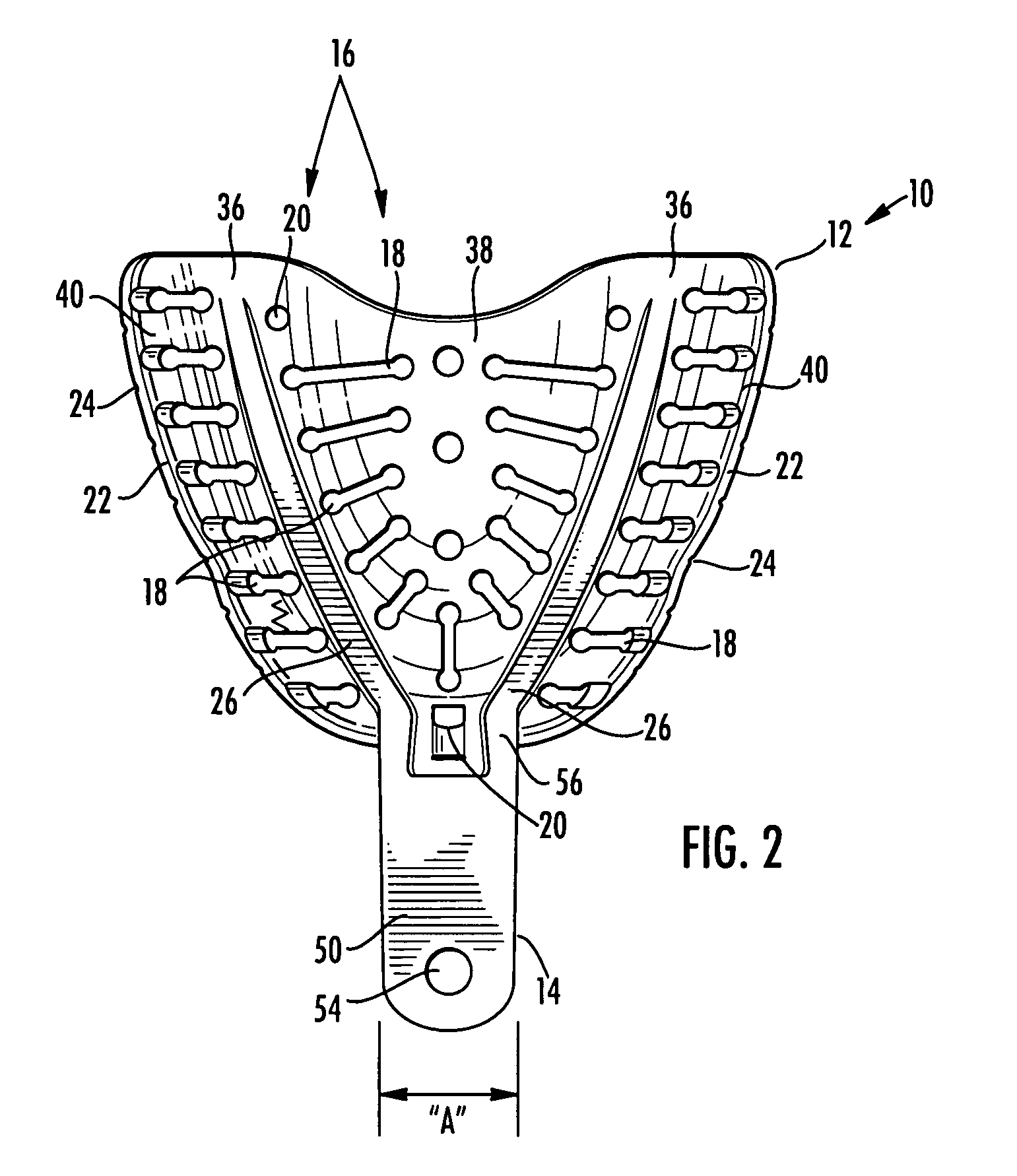
[0028]Referring to the figures of the drawings, wherein like numerals of reference designate like elements throughout the several views, particularly to FIG. 1, there is shown a top view of a dental impression tray 10 to be used in combination with an impression material or a combination of impression materials for obtaining an impression of the jaw and gingiva areas of the mouth of an edentulous patient, where the impression material is not shown. As shown in FIGS. 1 through 12, the dental impression tray 10 comprises a body 12, at least two finger rest beams 26, and a handle 14. As shown in FIG. 1, the body 12 has a body front end 28, a body rear end 30, a predetermined shape of the body 12, and a plurality of body openings 16. FIGS. 1 through 6 show one embodiment of the invention and FIGS. 7 through 12 show a second embodiment of the invention. The predetermined shape of the body 12 accommodates the anatomical shape of the edentulous patient's mouth and is dimensioned and config...


PUM


Abstract

A dental tray having a body, at least two finger rest beams and a handle. The body has a predetermined shape and a plurality of body openings. The predetermined shape of the body accommodates the anatomical shape of the patient's mouth and receives the entire jaw and gingiva areas. The plurality of body openings positioned in the body to allow the impression materials to vent through the body openings to obtain the impression and to retain the impression materials onto the body. The handle is received on the body and has a predetermined configuration to facilitate ease of use and elimination of lip pressure. Each finger rest beams are received longitudinally on the bottom of the body. The combination of the handle and each finger rest beams are ergonomically designed to allow optimal stabilization pressure be exerted by the operator to the dental tray and impression material.

Description

CROSS REFERENCE TO RELATED APPLICATION AND BENEFIT OF EARLIER FILING DATE[0001]This application is based upon U.S. Provisional Patent No. 60 / 667,632 filed on Apr. 2, 2005 entitled “Dental Tray For Obtaining Dental Impression Of Edentulous Patient”. This U.S. Letters Patent Application is claiming the benefit of the Apr. 2, 2005 filing date under 35 U.S.C. Section 119(e).BACKGROUND OF THE INVENTION[0002]1. Field of the Invention[0003]This invention relates to a new dental impression tray, used in combination with moldable material, for obtaining an accurate impression of the jaw and gingiva areas of the mouth of an edentulous patient.[0004]2. Prior Art[0005]In dentistry, an impression is often used to create an imprint likeness of an edentulous patient's jaw and gingiva areas in preparation for restoration of dental structures such as complete or partial dentures. The ability of the dental technician or dentist, hereinafter referred to as “operator”, to obtain a satisfactory impressi...

Claims


Application Information

Patent Timeline
Patent Type & Authority Patents(United States)
IPC IPC(8): A61C9/00
CPCA61C9/0006
Inventor MASSAD, JOSEPH JAMES
Owner GLOBAL DENTAL IMPRESSION TRAYS
Why Eureka
Try Eureka