Optical surface for wide-angle imaging

a wide-angle imaging and optical surface technology, applied in the field of optical surface for wide-angle imaging, can solve the problems of not being convenient, affecting the quality of the image, so as to reduce the magnitude of the error distance, and reduce the value of a single measure of overall error.

Inactive Publication Date: 2009-01-15
E QUIP SCI SERVICES
View PDF3 Cites 0 Cited by
  • Summary
  • Abstract
  • Description
  • Claims
  • Application Information

AI Technical Summary

Benefits of technology

[0016]Accordingly, the invention mitigates the effects of distortion introduced by wide-angle optical imaging surfaces by enabling the type and degree of distortion introduced by a surface designed in accordance with the method to be controlled through the use of the object model and the magnification profile. By appropriate selection of the model, to include salient features of the object to be viewed in the optical surface, and the magnification profile, the optical surface may be custom-designed to ensure that any distortion introduced is of an acceptable nature in view of the intended application of the optical surface.
[0017]For example, in the case of a golf mirror the optical surface may be designed to ensure that when a golfer observes the image of their own golf swing in the mirror, the apparent perspective of the reflected image is of sufficiently natural appearance to enable the golfer to correctly judge the quality of their swing, in order to make any necessary corrections. As another example, the inventive method may be used to define an optical surface for use in a wide-angle rear-view mirror for a motor vehicle, such that the relative location of other vehicles, or other objects, within the critical region of the image (ie close in to the driver's vehicle, which would normally be a blind zone if a plane mirror is used) provides a substantially correct impression of the relative location and distance.
[0029]modifying the optical surface to reduce a magnitude of the error distances.
[0030]In some embodiments of the invention, it may be possible to modify the optical surface so as to simultaneously reduce all error distances. Alternatively, the goal of modification may be to reduce a value of a single measure of overall error. For example, a suitable measure of overall error may be the mean square distance between image points and corresponding points on the ideal image, and the goal of modification may be to reduce the mean square distance.
[0031]In a preferred embodiment, the modification of the optical surface includes applying a stretch to the surface along an axis thereof, such that a projected distance between each image point and corresponding point on the ideal object image along said axis is reduced or eliminated.
[0041]The continuously varying curvature may be selected such that the surface is modified with respect to a reference surface for which the magnification is substantially equal to the predetermined magnification profile, such that an error distance, defined as a distance in image space between points of an image of the object model and corresponding points of an ideal object image, is reduced relative to a corresponding error distance of an image produced by said reference surface. For example, in preferred embodiments, the surface is stretched along an axis thereof such that a projected distance between each image point and a corresponding point on the ideal object image onto said axis is reduced or eliminated.

Problems solved by technology

However, it may not be convenient, particularly when practising outdoors, to provide a large, plane mirror.
However, a common problem of all of the aforementioned types of wide-angle optical imaging apparatus is the distortion of the resulting image that typically occurs.
Similar forms of image distortion may occur with the use of convex mirrors.
While such distortion may be deliberately employed, for example to produce interesting photographic effects, or as a form of entertainment, such as in carnival mirrors, generally such distortion is undesirable.
For example, the distortion resulting from the use of convex rear-vision mirrors makes the location and distance of vehicles observed in the mirror difficult to judge.
As a consequence, for safety reasons the use of such mirrors in motor vehicles is generally limited by legislation and, in many jurisdictions, convex mirrors may only be used for the passenger-side rear-vision mirror.
Similarly, in a training application, such as the case of the golf mirror described previously, the use of a convex mirror results in a loss of correct perspective of the image observed in the mirror.
This tends to cause those parts of the golfer's body, such as their legs, which are closer to the mirror to appear exaggerated in size as compared with more distant parts of the body.
Since a significant portion of the image that is of interest to a golfer observing their own golf swing relates to the upper part of the body, this loss of correct perspective is a disadvantage that may significantly offset the benefits of using a mirror for self observation.

Method used


Image

  • Optical surface for wide-angle imaging
  • Optical surface for wide-angle imaging
  • Optical surface for wide-angle imaging

Examples


Embodiment Construction

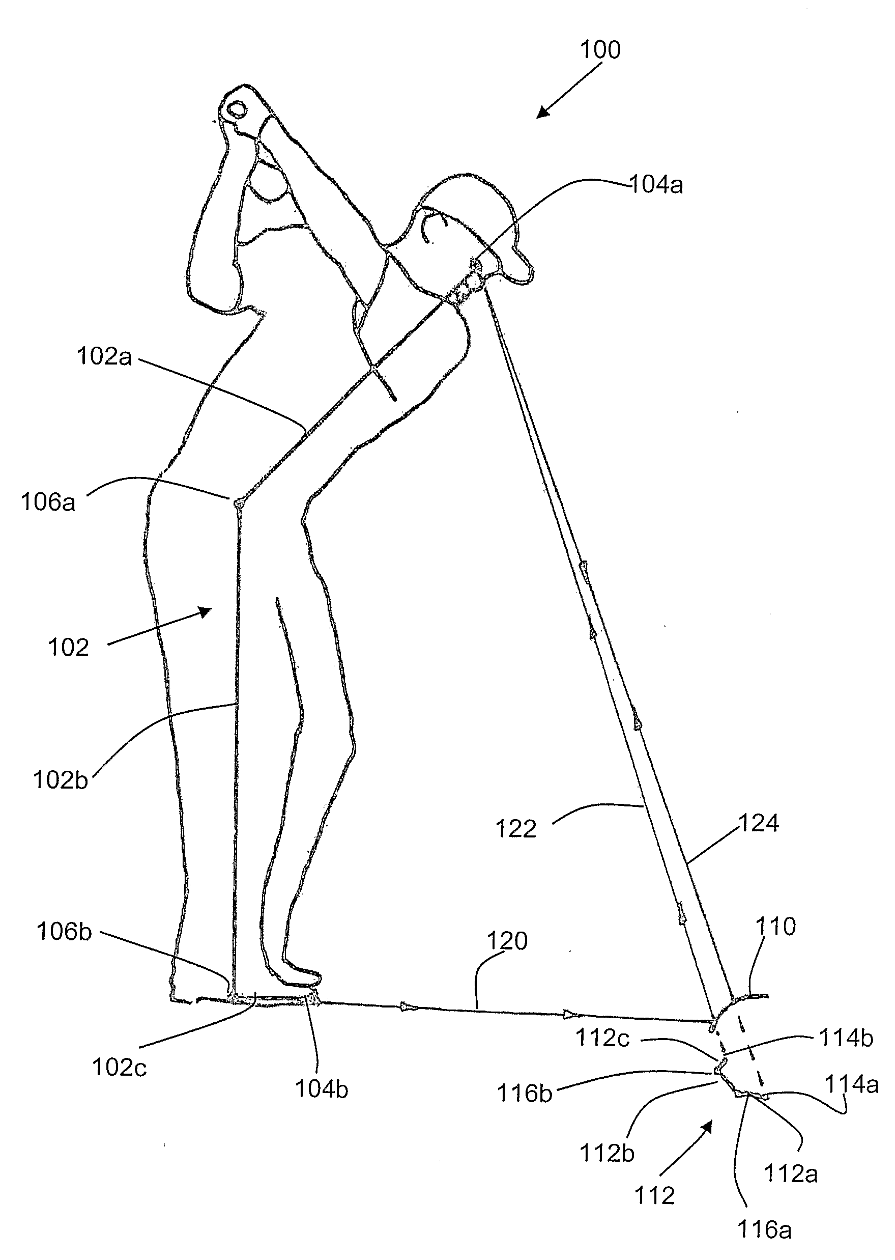
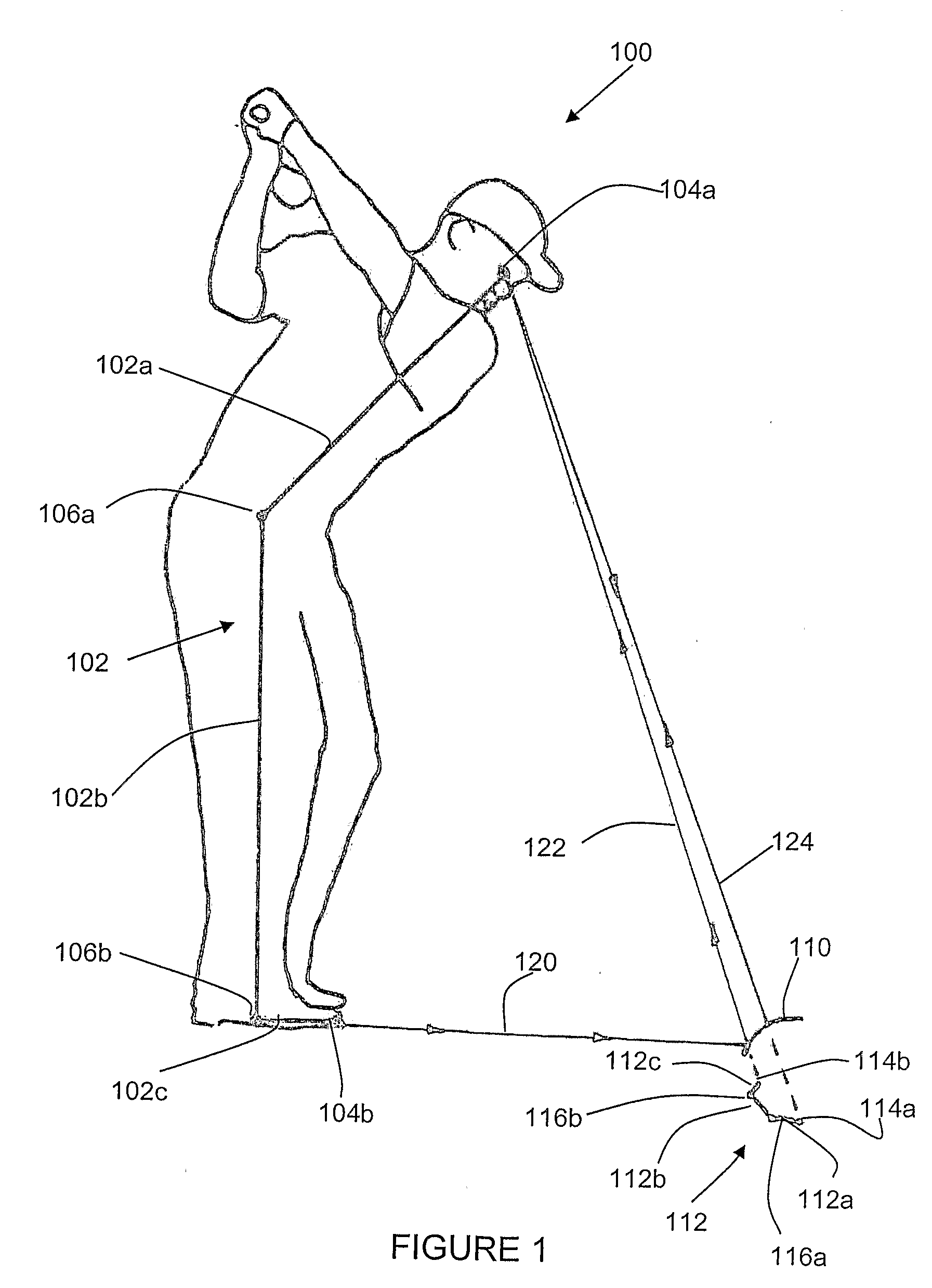
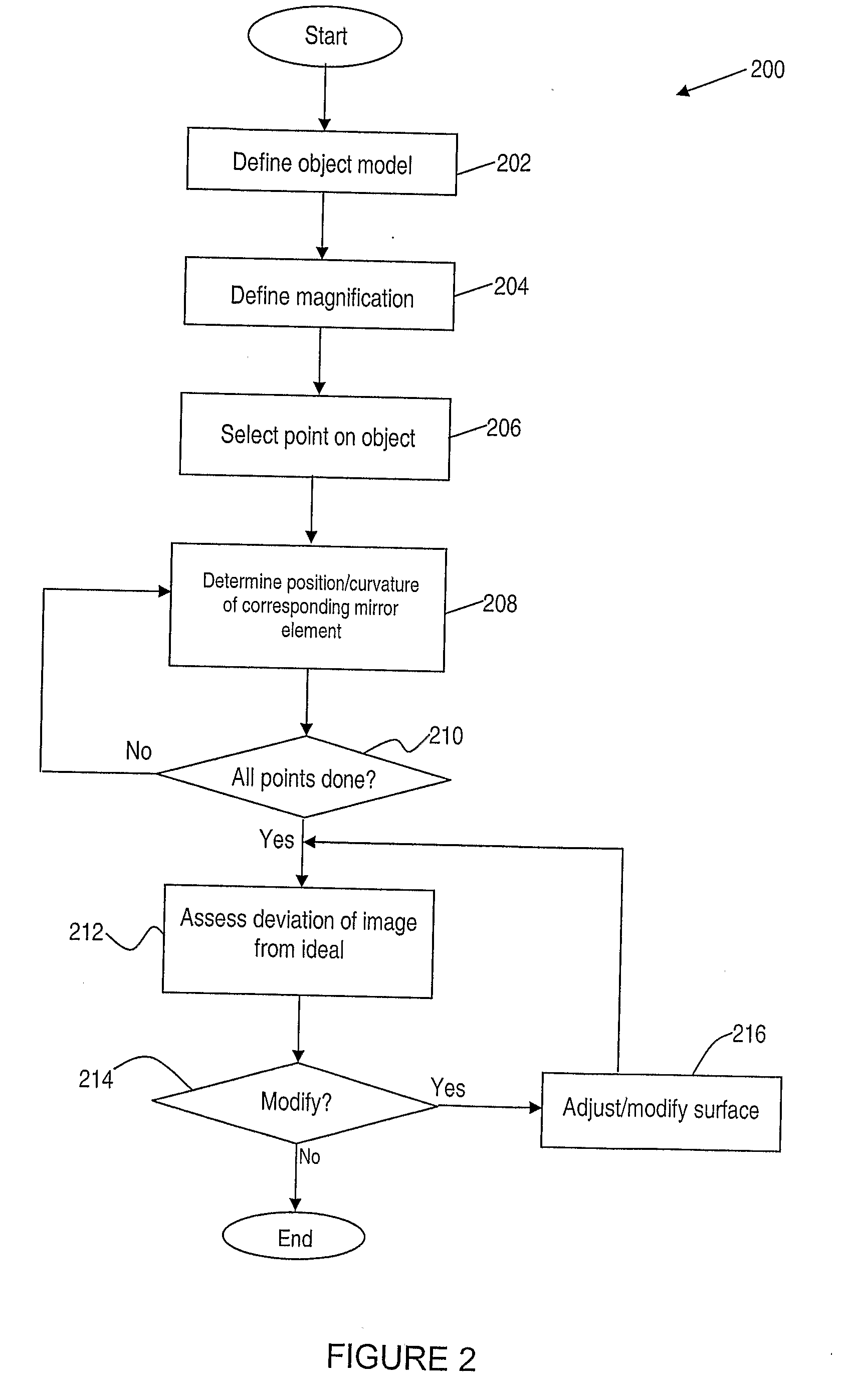
[0052]The present invention is directed to a method of designing an optical surface for producing an image of an object, and to optical apparatus including optical surfaces designed in accordance with the method. A preferred embodiment, and variations thereof, is described with reference to the particular example of a golf practice mirror, wherein the relevant optical surface is the reflective surface of the mirror. However, it will be appreciated by those skilled in the art that the method of the present invention may be used to design a variety of optical surfaces for use in different applications, including applications of both mirrors and lenses, and not limited to the specific example of a golf mirror disclosed herein. For example, embodiments of the design method, and optical surfaces designed thereby, could be used in other applications, such as providing wide-view rear-vision mirrors for use in motor vehicles. Other potential applications of the invention, and embodiments th...


PUM


Abstract

A method of designing an optical surface (110) for producing an image of an object (100) includes defining an object model (102) representing the object (100) that includes a plurality of object points. A magnification profile is defined which specifies a desired transverse magnification factor for at least each of said object points. For each object point of the object model, the method includes determining a curvature of the optical surface (110) at a point along at least one axis thereof, such that a magnification of an image (112) of the object model (102) at a corresponding image point corresponds with the desired magnification factor of the magnification profile. The optical surface (110) is then selected to have a substantially continuously varying curvature along the axis, and to include the determined surface point curvatures. Optical imaging apparatus including surfaces designed in accordance with the method are also provided. An exemplary embodiment of the invention provides a golf practice mirror which may be placed behind a golf ball relative to a golfer thereby enabling the golfer to view his or her swing, grip, stance and so forth, and substantially mitigating various undesirable forms of distortion characteristic of prior art practice mirrors.

Description

FIELD OF THE INVENTION[0001]The present invention relates to optical imaging apparatus, and more particularly to optical apparatus, such as mirrors or lenses, which include surfaces designed to provide wide-angle imaging.BACKGROUND OF THE INVENTION[0002]It is known to use optical apparatus, such as purpose-designed mirrors or lenses, to provide a wide-angle view in various circumstances in which such a view may be beneficial.[0003]For example, wide-angle mirrors, typically having a convex surface, are used to provide an increased viewing angle in various applications. For example, slightly convex mirrors are sometimes provided as passenger side mirrors on motor vehicles, in order to increase the viewing angle available to the driver, and minimise the passenger-side blind zone.[0004]Another application of such mirrors arises in relation to providing visual feedback during training of individuals, such as in sports training. In one particular example, a golfer may wish to assess and c...

Claims


Application Information

Patent Timeline
Patent Type & Authority Applications(United States)
IPC IPC(8): G02B5/10
CPCG02B17/02A63B69/3623A63B69/3667A63B2071/0694A63B2225/12A63B69/3629
Inventor JENKINS, GRAEME
Owner E QUIP SCI SERVICES
Why Eureka
Try Eureka