System and method for correcting optical distortions when projecting 2d images onto 2d surfaces

a technology of optical distortion and projecting image, which is applied in the field of projecting images, can solve the problems of not allowing the materiality of such publications and patent documents to be patentable, and achieve the effects of reducing the artifactual effect of uniformity and brightness, reducing the keystone and/or “pincushion”, and reducing the effect of optical distortion

Active Publication Date: 2015-05-07
MARADIN
View PDF3 Cites 7 Cited by
  • Summary
  • Abstract
  • Description
  • Claims
  • Application Information

AI Technical Summary

Benefits of technology

[0009]Certain embodiments of the present invention seek to reduce keystone and/or “pincushion” optical distortion effects in which straight lines are bowed towards the center point of a projected image.
[0010]Certain embodiments of the present invention seek to reduce optical distortion effects in which laser-generated light spots (pixels) are distributed non-uniformly rather than at equal intervals along the ho

Problems solved by technology

Materiality of such publications and patent

Method used


Image

  • System and method for correcting optical distortions when projecting 2d images onto 2d surfaces
  • System and method for correcting optical distortions when projecting 2d images onto 2d surfaces
  • System and method for correcting optical distortions when projecting 2d images onto 2d surfaces

Examples


embodiment 1

[0015]A method for projecting 2D images represented by pixels onto a 2D surface, using at least one laser which generates at least one coherent beam and is arranged to impinge upon at least one micro-mirror arranged for pivoting, at non-uniform angular velocity, about two axes, so as to reflect the coherent beam sequentially over the entirety of said 2D surface,

[0016]a. the method comprising:

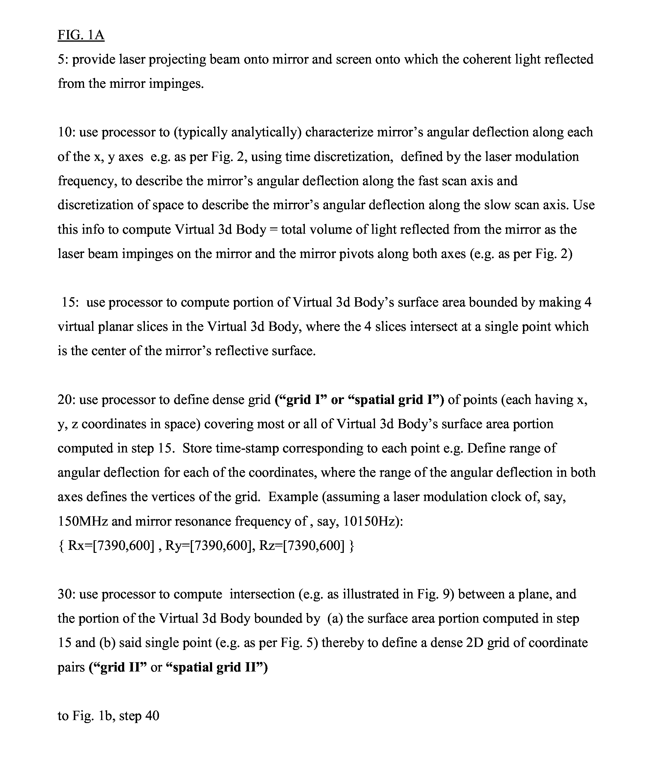
[0017]b. providing a computerized representation of a first, dense, grid of spatial 3D coordinates comprising a multiplicity of angular orientations of the mirror given a specific predefined operating modulating frequency of the laser; where the spatial 3D coordinates in space respectively correspond to a set of time-points that are evenly distributed along a time-dimension with constant time-discretization deltaT;

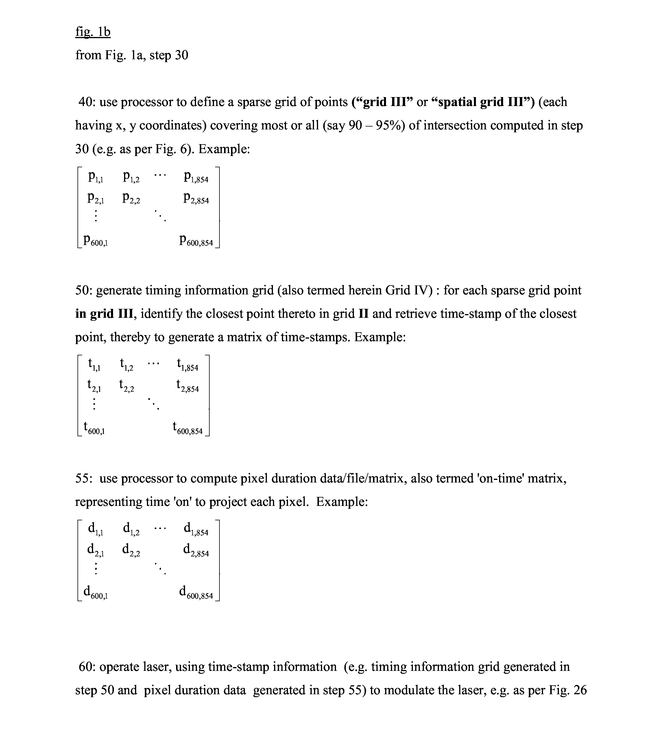
[0018]c. deriving a dense 2D representation of an image, comprising a dense grid of first coordinate pairs, from said first, dense, grid of spatial 3D coordinates, where the coordinate...

embodiment 2

[0022]A method according to any of the preceding embodiments wherein said providing a first, dense, grid includes computing the micro-mirror's pivoting motion as a function of the laser's modulation frequency.

embodiment 3

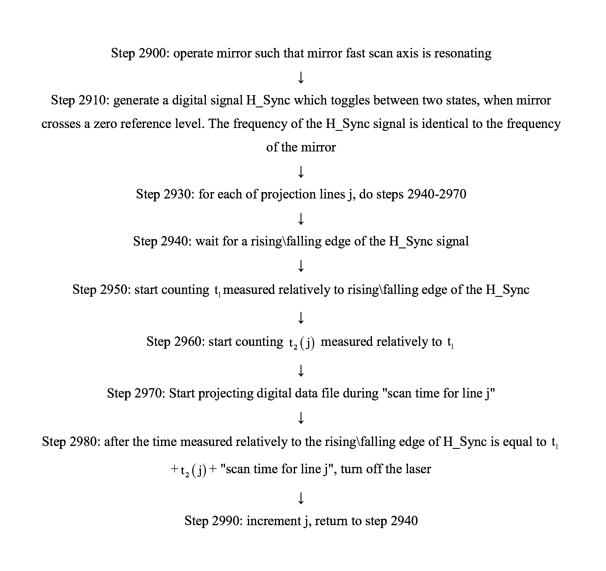
[0023]A method according to any of the preceding embodiments wherein said pre-selecting comprises generating, and said operating comprises receiving, data indicating points in time at which pixel centers are to be projected.


PUM


Abstract

A system for projecting 2D images, providing a computerized representation of a first, dense, grid of spatial 3D coordinates which respectively correspond to a set of time-points evenly distributed along a time-dimension with constant time-discretization; deriving a dense 2D representation of an image, whose coordinate pairs respectively correspond to said set of time-points; d. Defining a sparse 2D grid of second coordinate pairs, spaced such that distances between any two adjacent coordinate pairs along a row of said sparse 2D grid are constant; and finding, coordinate pairs closest to the second sparser grid to yield a third grid, and a laser controller to control the laser to project a digitally represented image, from said distance, timed to project pixels whose locations respectively correspond to the subset of uniformly distanced positions forming said third grid, thereby to prevent image distortion despite non-uniformity of micro-mirror's angular velocity.

Description

REFERENCE TO CO-PENDING APPLICATIONS[0001]Priority is claimed from:[0002]U.S. provisional application No. 61 / 654,817, entitled “A method for projected image pixel and brightness uniformity” and filed 2 Jun. 2012; and[0003]PCT Application No. PCT / IL2012 / 050351 “Apparatus and methods for locking resonating frequency of a miniature system”.FIELD OF THIS DISCLOSURE[0004]The present invention relates generally to projecting images and more particularly to use of lasers for projecting images.BACKGROUND FOR THIS DISCLOSURE[0005]Conventional technology constituting background to certain embodiments of the present invention is described in the following publications inter alia:[0006]Smart glasses are known and are described e.g. on Google's website at google.com / glass / start / how-it-feels.[0007]The disclosures of all publications and patent documents mentioned in the specification, and of the publications and patent documents cited therein directly or indirectly, are hereby incorporated by ref...

Claims


Application Information

Patent Timeline
IPC IPC(8): H04N5/74
CPCH04N5/7458H04N9/3185G02B26/101G03B21/008G03B21/147G03B21/2033H04N9/3129H04N9/3161
Inventor NAFTALI, MATANHORNSTEIN, SHARONYEHIEL, MENASHE
Owner MARADIN
Why Eureka
Try Eureka