Image pick-up apparatus and image restoration method

A camera device and image technology, applied in image communication, TV, color TV components and other directions, can solve problems such as inability to restore images

Inactive Publication Date: 2006-01-25
OLYMPUS CORP
View PDF1 Cites 6 Cited by
  • Summary
  • Abstract
  • Description
  • Claims
  • Application Information

AI Technical Summary

Problems solved by technology

Therefore, when the vibration locus is calculated simply by calculation in the paraxial region, the calculated vibration locus is different from that in the camera unit (CCD), so that the image cannot be accurately restored on the entire screen

Method used


Image

  • Image pick-up apparatus and image restoration method
  • Image pick-up apparatus and image restoration method
  • Image pick-up apparatus and image restoration method

Examples


no. 1 example

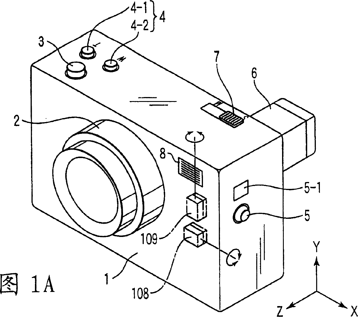
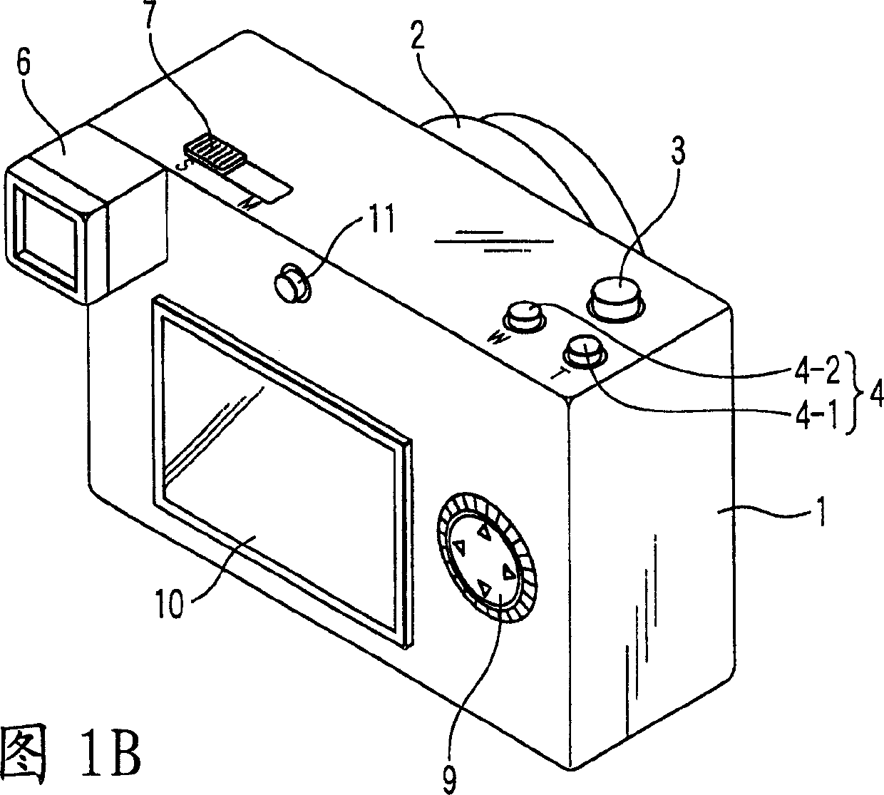
[0077] 1A is a front surface perspective view of a digital video camera as an example of an imaging device according to a first embodiment of the present invention, and FIG. 1B is a rear surface of a digital video camera as an example of an imaging device according to a first embodiment of the present invention perspective.

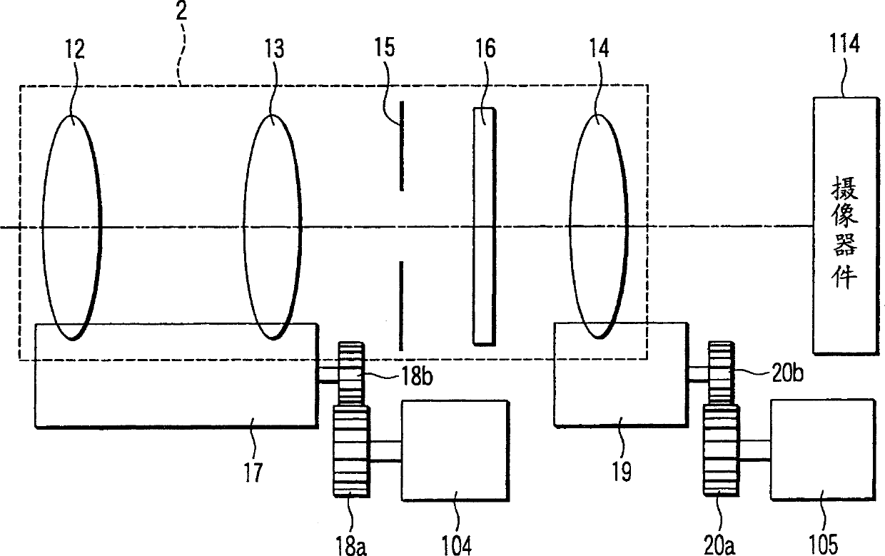
[0078] As can be seen from FIG. 1A , the lens unit 2 is connected to the front surface of the camera body 1 . It can be seen from FIG. 1B that the viewfinder 6 is integrated with the rear surface of the camera body 1 . The lens unit 2 includes a plurality of lenses for imaging, and a drive unit. The lens unit 2 will be described in detail below with reference to FIG. 2 .

[0079] When a release switch 3 is pressed (turned on), the imaging operation is started. The zoom switch 4 includes a T button 4-1 and a W button 4-2. When the T button is pressed, the magnification of the photographing lens is changed to the telescope side. When the W button is pr...

no. 2 example

[0115] Even in a video camera having a shake correction unit in which a restoration operation is performed from image data after a still image is captured, the shake correction unit for performing the above-mentioned type of image restoration operation cannot be applied to a through-image display for Observing objects in preparation for still image shooting. Even when this unit is employed, the intended effect cannot be obtained. In order to solve this problem, in the second embodiment, vibration correction that differs with the still image shooting time and the through image display time is performed, as shown in FIGS. 7 , 8 . That is, vibration correction for a moving image (through image) is performed when a through image is displayed, and a different type of vibration correction for a still image is performed when a still image is captured. Also, the through image in the still image mode differs from the through image in the moving image mode in the clipping range of the ...

no. 3 example

[0119] A third embodiment will be described below with reference to FIGS. 9 to 12 . In this embodiment, with regard to captured images, after lens distortion correction is performed, electronic vibration correction for still images and electronic vibration correction for moving images are performed. Here, FIG. 9 is a block diagram of a digital camera control circuit. As shown in FIG. 9, the difference between the third embodiment and the embodiment of FIG. 3 is that the correction value memory 118 and the track correction circuit 121 are omitted, and the distortion correction value memory 171 (distortion information storage unit, image degradation information storage unit) is added at the same time. storage unit) and an image distortion correction circuit 172 as constituent elements. It should be noted that in the third embodiment, except for FIG. 3 , FIGS. 1 to 8 are commonly referred to by the first and second embodiments. In addition, the third embodiment differs from the...


PUM


Abstract

The present invention provides an image pick-up apparatus and iamge recoery method. The image pick-up apparatus includes an optical system which forms a subject image. An image pick-up unit obtains image data from the subject image formed by the optical system. A vibration detecting unit detects a vibration of the image pick-up apparatus. In an image deterioration information storage unit, information of image deterioration generated by the optical system is stored. An image deterioration correcting unit corrects the image deterioration generated by the optical system with respect to the image data output from the image pick-up unit in accordance with the image deterioration information stored in the image deterioration information storage unit. A vibration restoring unit restores the image deteriorated by the vibration with respect to the image data output from the image deterioration correcting unit in accordance with the vibration detecting signal of the time series.

Description

technical field [0001] The present invention relates to an imaging device and an image restoration method in which vibration is detected to restore a blurred image to a blur-free image. Background technique [0002] In an imaging device such as a digital camera, a video camera, etc., an image degraded by vibration at the time of imaging is corrected to restore an image close to the original image. For example, in a digital video camera (hereinafter sometimes simply referred to as a video camera), when correcting a vibration in a still image or the like, an angular velocity sensor or the like is used to detect a locus of camera shake at the time of imaging, and after imaging is performed based on the detected shake locus. Scheduled image restoration operations. [0003] It has been proposed to use a point spread function (PSF) to correct for vibrations in the process of restoring an image without any blurring. When utilizing this point spread function, the image can be rest...

Claims


Application Information

Patent Timeline
Patent Type & Authority Applications(China)
IPC IPC(8): H04N5/232
CPCH04N5/23274H04N5/23248H04N23/68H04N23/6842
Inventor 大久保光将日暮正树半川雅司今井右二
Owner OLYMPUS CORP
Why Eureka
Try Eureka