Wavelength calibration method of optical spectrum instruments

A spectrum and instrument technology, applied in the field of wavelength calibration of spectroscopic instruments, can solve the problems of spectral image skew, wavelength accuracy limitation, and limited spectral image sampling rate.

Inactive Publication Date: 2008-04-09
TSINGHUA UNIV
View PDF0 Cites 22 Cited by
  • Summary
  • Abstract
  • Description
  • Claims
  • Application Information

AI Technical Summary

Problems solved by technology

In spectroscopic instruments using array detectors, the accuracy of the spatial position of the spectral peaks used for fitting is limited due to the following problems, which limits the wavelength accuracy of the calibration results
[0004] First of all, the pixel interval of the detector (that is, the sampling interval of the spectral image) cannot be infinitely small, so the sampling rate of the spectral image is limited, and a lower sampling rate will cause the data points detected by each spectral line to be too sparse , the obtained spectrogram cannot accurately reproduce the spectral line profile, which affects the accurate determination of the spatial position of the spectral peak
[0005] Secondly, the width of the detector pixel (i.e., the integration interval at the sampling point) cannot be infinitely small, and an excessively large integration interval will bring serious blur to the spectrogram, broaden the spectral line profile on the spectrogram, and also affect the spectral peak Accurate determination of spatial location
[0006] In addition, limited by the size of the optical path structure and the manufacture of optical components, the optical system of the instrument cannot completely eliminate aberrations, and these aberrations will cause the spectral image to be skewed, which may cause problems when judging the central wavelength position of a spectral line during the calibration process. offset
[0007] In the existing wavelength calibration method, the spatial position of the spectral peak is obtained under the constraints of the above conditions, and the wavelength accuracy of the calibration results will also be limited

Method used


Image

  • Wavelength calibration method of optical spectrum instruments
  • Wavelength calibration method of optical spectrum instruments
  • Wavelength calibration method of optical spectrum instruments

Examples


Embodiment 1

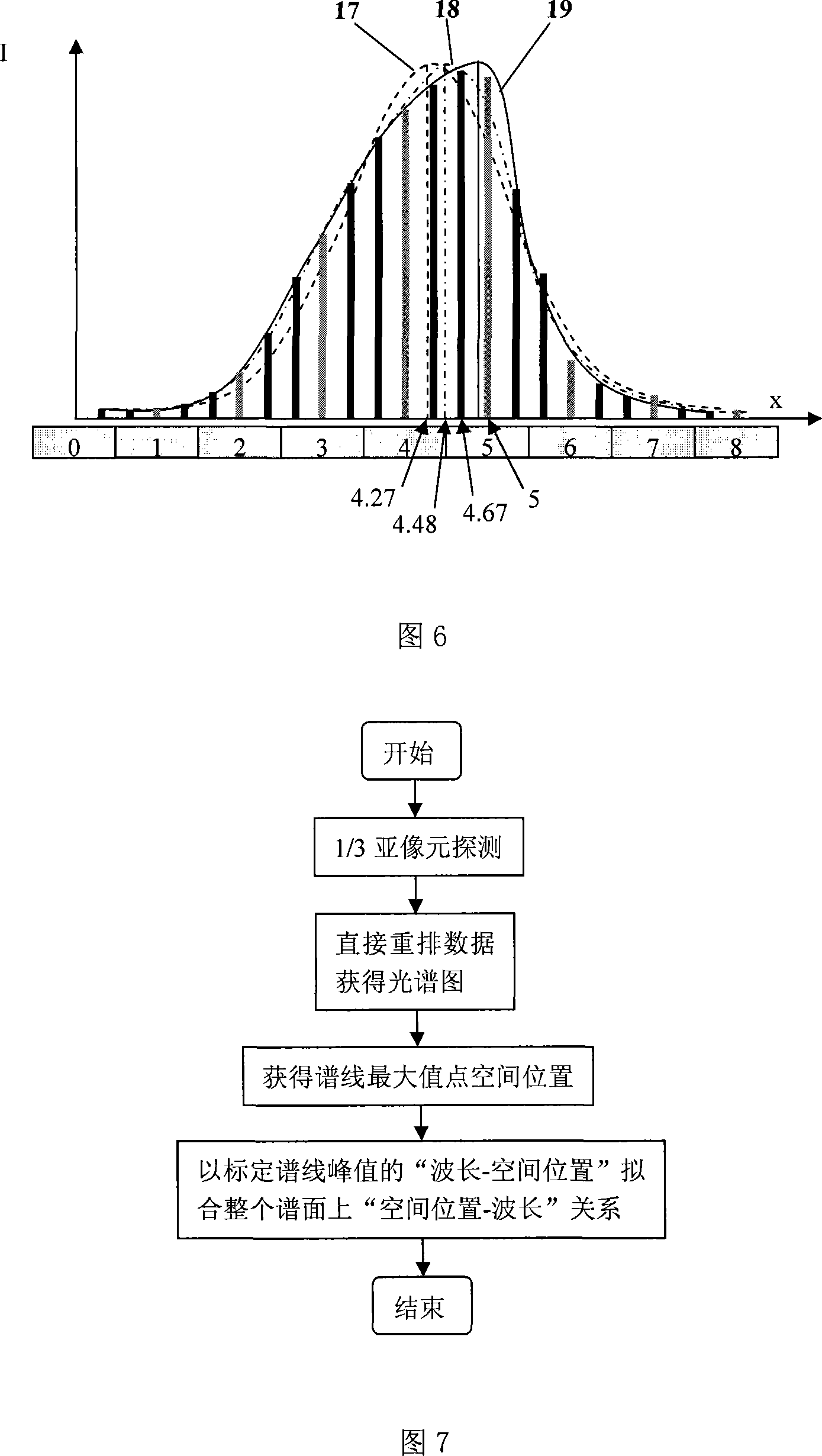
[0026] In the new wavelength calibration method according to this patent, a fixed spectral image is used, and the detector is moved at a step distance of 1 / 3 pixel to realize 1 / 3 sub-pixel detection; the data is directly rearranged to reconstruct the spectral map; the spatial position of the spectral peak It is represented by the sub-pixel position of the maximum point of each spectral line data in the reconstructed spectrogram. The specific flow chart is shown in Figure 7.

[0027] Table 1 shows the comparison of the wavelength accuracy at some spectral lines under a set of experimental results and the wavelength accuracy under the existing method. Compared with the wavelength accuracy of existing methods, the wavelength accuracy of the new method is improved by about 30% on average.

[0028] Table 1. Comparison of the wavelength accuracy of the calibration results between the existing method and the new method of Example 1 (unit: nm)

[0029] Detection line wavele...

Embodiment 2

[0031] In the new wavelength calibration method according to this patent, fixed detectors and rotating gratings are used to move the spectral image relative to the detector by 1 / 3 pixel interval to achieve 1 / 3 sub-pixel detection; the average band-limited recursion is used to obtain sub-pixels The detection value reconstructs the spectrogram; the spatial position of the spectral peak is represented by the spatial position corresponding to the maximum value after Gaussian fitting of the spectral line profile. The specific flow chart is shown in Figure 8.

[0032] Table 2 shows the comparison of the wavelength accuracy at some spectral lines under a set of experimental results and the wavelength accuracy under the existing method. Compared with the wavelength accuracy of existing methods, the wavelength accuracy of the new method is improved by about 80%.

[0033] Table 2. Comparison of the wavelength accuracy of the calibration results between the existing method of Example 2 ...


PUM


Abstract

A wavelength calibration method of spectral instrumentation mainly relating to wave length calibration method adopting spectral instrumentation of array detector pertains to the filed of wave length calibration technology of spectral instrumentation. The spectral instrumentation of the method adopts array detectors and lighting source of linear spectra, spatial locations of every spectrum peak of the lighting source are acquired from the spectrogram output from the instrumentation, and the 'spatial location - wave-length relationship' on the power spectrum is fitted by according these spectrum peak wavelength and the corresponding spatial locations thereof, thus corresponding wavelength of every pixel of the detector is confirmed, the spatial locations of every spectrum peak of the lighting source is acquired through processes as following: sub-pixel detecting; sub-pixel reestablishing; spectrum peak spatial locations acquiring. The sub-pixel detecting of the invention increases sampling ratio of spectrogram, spectrogram with improved resolution in acquired; the comprehensive applications of sub-pixel detecting, sub-pixel reestablishing and spectrum contour fitting further increases the wavelength accuracy of spectral instrumentation with array detectors step by step. The invention has prominent effect.

Description

technical field [0001] The invention relates to a wavelength calibration method of a spectroscopic instrument using an array detector, and belongs to the technical field of spectroscopic instrument wavelength calibration. Background technique [0002] A spectroscopic instrument using an array detector can be abstracted into a model as shown in Fig. 1 . The light emitted by the light source (1) is limited by the incident aperture (2), collimated by the collimator (3), projected onto the grating (4), and converged by the imaging mirror (5) into a spectral image on the spectral surface after dispersion. Detect by detector (6) again, output spectrogram. According to the principle of the detector, the spectrogram is obtained by integrating the spectral image with the detector pixel, and the interval is the width of the photosensitive surface of the pixel, and the sampling interval is the pixel interval. Accompanying drawing 2 is a schematic diagram of integral sampling of a spe...

Claims


Application Information

Patent Timeline
Patent Type & Authority Applications(China)
IPC IPC(8): G01J3/12G01J3/18G01J3/28G01J3/10
Inventor 杨怀栋黄星月何庆声
Owner TSINGHUA UNIV
Why Eureka
Try Eureka