Beam Scanner for Autonomous Vehicles

a beam scanner and autonomous vehicle technology, applied in the field of vision systems, can solve the problems of low frequency of scans, limited field of regard, and inability to operate the self-driving vehicle with any degree of safety, and achieve the effects of low power consumption, high sampling rate, and large field of regard

Active Publication Date: 2018-08-02
ALBELO JEFFREY +1
View PDF4 Cites 39 Cited by
  • Summary
  • Abstract
  • Description
  • Claims
  • Application Information

AI Technical Summary

Benefits of technology

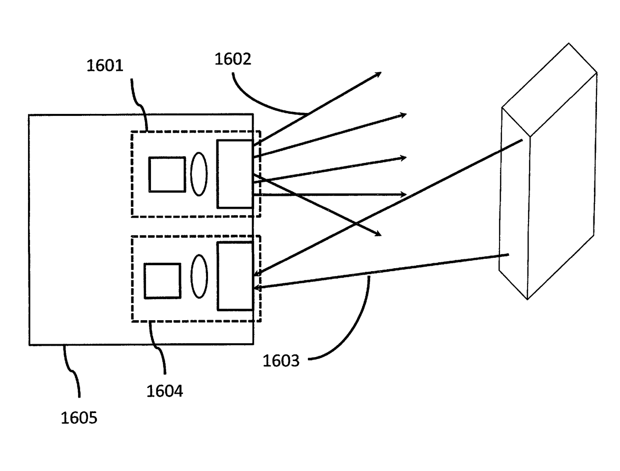
[0008]In accordance with various embodiments, an operational guidance or vision system for a autonomous vehicle is provided. It will have low power consumption, a large field of regard and a very high sampling rate; much faster than liquid crystal systems.

Problems solved by technology

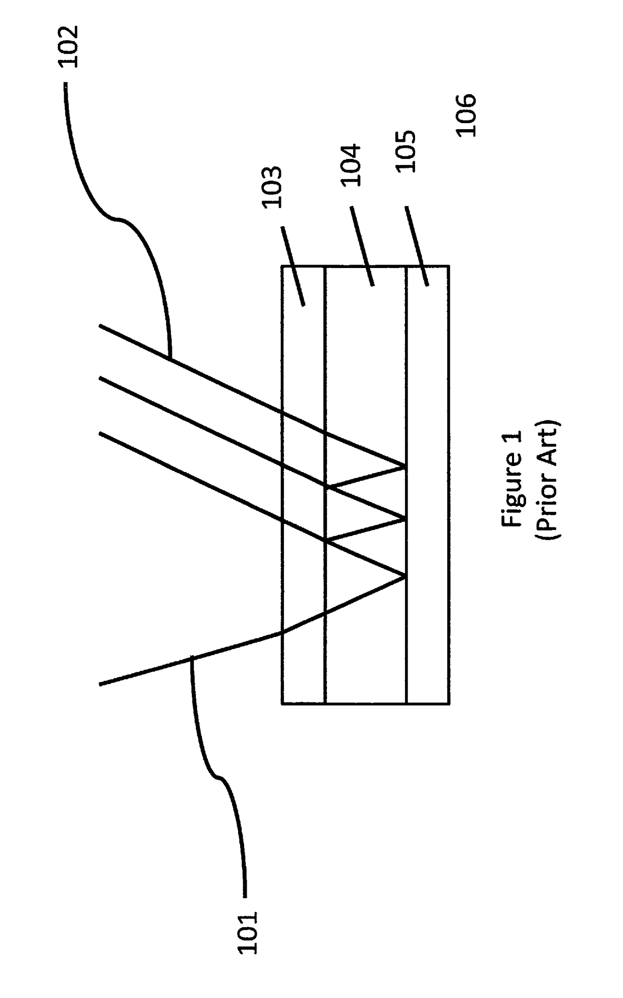
However, none of these are particularly well suited to operating the self-driving vehicle with any degree of safety for two reasons: First, the frequency of their scans is too low, and second, their field of regard (also called instantaneous field of view, IFOV) is limited.
Any improved systems would have to be physically larger (and heavier), and would require much faster movement of the equipment to accomplish the desired, faster scan rate; this is a serious detriment to all vehicles, especially those that are fully electric.
Although the transportation industry is only recently focused on autonomous modes of operation, the military has long been studying these and related problems.

Method used


Image

  • Beam Scanner for Autonomous Vehicles
  • Beam Scanner for Autonomous Vehicles
  • Beam Scanner for Autonomous Vehicles

Examples


Embodiment Construction

[0027]While various aspects and features of certain embodiments have been summarized above, the following detailed description illustrates at least on exemplary embodiment in further detail to enable one skilled in the art to practice such an embodiment. The described example is provided for illustrative purposes and is not intended to limit the scope of the invention.

[0028]In the following description, for the purposes of explanation, numerous specific details are set forth in order to provide a thorough understanding of the described embodiment / s. It will be apparent to one skilled in the art, however, that other embodiments of the present invention may be practiced without some of these specific details. Certain structures and devices may be shown in block diagram form. While various features are ascribed to different embodiments, it should be appreciated that the features described with respect to one embodiment may be incorporated with other embodiments as well. By the same tok...


PUM


Abstract

A light beam steering transmissive element with an arbitrarily sized aperture comprising at least one layer of a insulating matrix modified for increased polarizability under electrical, magnetic or optical stimulation, between two or more substrates that can be electrically configured to provide signal modulation (optical, magnetic or electrical) that will control the wavefronts of incident light, thereby taking off-axis electromagnetic signals and aligning them to the aperture of a receiving element positioned near the device, or the reverse, sending signals originating behind the steering device to a variety of user-defined angles in two or more dimensions.

Description

COPYRIGHT STATEMENT[0001]A portion of the disclosure of this patent document contains material that is subject to copyright protection. The copyright owner has no objection to the facsimile reproduction by anyone of the patent document or the patent disclosure as it appears in the Patent and Trademark Office patent file or records, but otherwise reserves all copyright rights whatsoever.FIELD[0002]The present disclosure relates, in general, to a vision system for the transmission and reception of LIDAR signals, and more particularly directed for use in the navigation systems of autonomous vehicles.BACKGROUND[0003]Autonomous vehicles are now reality on the battlefield and widespread acceptance and implementation are on the immediate horizon in other theaters of operation. The accuracy and precision of these self-driving systems depend upon the footprint or map of the area and objects in the vicinity of the vehicle whether moving or stationary. For optimal performance and safety, the f...

Claims


Application Information

Patent Timeline
Patent Type & Authority Applications(United States)
IPC IPC(8): G01S17/93G01S17/02G01S7/484G01S17/931G01S17/04
CPCG01S17/936G01S7/484G01S17/026G01S17/42G01S7/4814G01S7/4816G01S7/4817G01S17/931G01S17/04
Inventor ALBELO, JEFFREYLACHAPELLE, JOSEPH
Owner ALBELO JEFFREY
Why Eureka
Try Eureka