Medical system using implantable sensor in bone for determining position coordinates

a technology of position determination and implantable sensors, which is applied in the direction of sensors, blood flow measurement, catheters, etc., can solve the problems of insufficient image speed, inability to accurately measure even on accurate images, and inability to accurately measure the size of organs, such as the heart, to achieve accurate measurement of organs and spaces within the human body

Inactive Publication Date: 2005-09-29
BEN HAIM SHLOMO +1
View PDF15 Cites 40 Cited by
  • Summary
  • Abstract
  • Description
  • Claims
  • Application Information

AI Technical Summary

Benefits of technology

[0010] It is an object of some aspects of the present invention to provide a method for accurate measurement of organs and spaces within a human body.
[0013] Another object of some aspects of the present invention is to provide a method of aligning bone fractures without unduly exposing the patient and staff to large amounts of radiation.
[0018] In some preferred embodiments of the present invention, the sensors are placed at a plurality of points on an outer or inner surface of an organ, while the position determining system continuously determines and records the coordinates of these points, preferably at a high sampling rate. The calculating circuitry calculates the size of the organ according to the recorded coordinates. Preferably, the sensors are mounted on the tip of one or more catheters, so as to allow easy movement of the sensors along the surface of the measured organ.
[0028] In order to calibrate the sensors before beginning the fixation, the region of a fracture is imaged using any suitable imaging method known in the art, such as fluoroscopy or MRI. Simultaneously, position coordinates of the sensors are determined and recorded using the position determining system. An image, preferably a three dimensional image, of the fracture pieces is displayed on a screen. The position coordinates of the sensors are registered with specific points in a coordinate frame associated with the image, and the contours of each piece are linked with the respective sensor. Preferably, each point in the image which represents part of a fracture piece is linked with one of the sensors. When the fracture pieces are moved, the display on the screen is updated according to the position coordinates of the sensors, which are updated continuously by the position determining system. Thus an on-line image of the bone fracture is produced, enabling easy alignment of the fracture, without requiring additional imaging.
[0029] In one of these preferred embodiments, during calibration, which is preferably performed after the patient's skin covering the bone is surgically opened, an external probe with a position sensor at its tip is passed over the surface of the fracture pieces. The position determining system determines and records the positions of a plurality of points on the surface of each piece, using the sensor within the tip of the external probe. The points on the surface of each piece are preferably registered relative to the sensor connected to the piece, so as to compensate for movements of the piece during calibration. Thus, for each fracture piece, the calculating circuitry records the coordinates of the sensor connected to the piece and coordinates of the plurality of points received during calibration, so that the position and shape of the entire piece can be determined based on the position and orientation of the position sensor fixed thereto. During alignment of the bone, the image of the bone is thus precisely updated.
[0045] Preferably, the method includes identifying a region of the area in which there is less than a predetermined density of determined points, and prompting a user to bring a sensor to the region to determine coordinates of additional points.

Problems solved by technology

However, these measurements are less accurate than direct measurements of the bone dimensions.
In addition, some organs have a complicated geometry and therefore are hard to measure even on accurate images.
Furthermore, some organs, such as the heart, are in movement and cannot be imaged fast enough to allow production of a clear and still image which can be measured.
The use of such arms is limited to organs which are easily accessible to the arm, and therefore in most cases this system cannot be used in minimally invasive procedures.
In addition, using more than one arm simultaneously is very difficult, since multiple arms interfere with each other.
However, when the fracture is complicated, many images may be necessary, causing the surgeon and patient to be exposed to large amounts of radiation.
However, this method requires producing a separate sub-image for each bone section, and therefore is not suitable for multiple fracture pieces.

Method used


Image

  • Medical system using implantable sensor in bone for determining position coordinates
  • Medical system using implantable sensor in bone for determining position coordinates
  • Medical system using implantable sensor in bone for determining position coordinates

Examples


Embodiment Construction

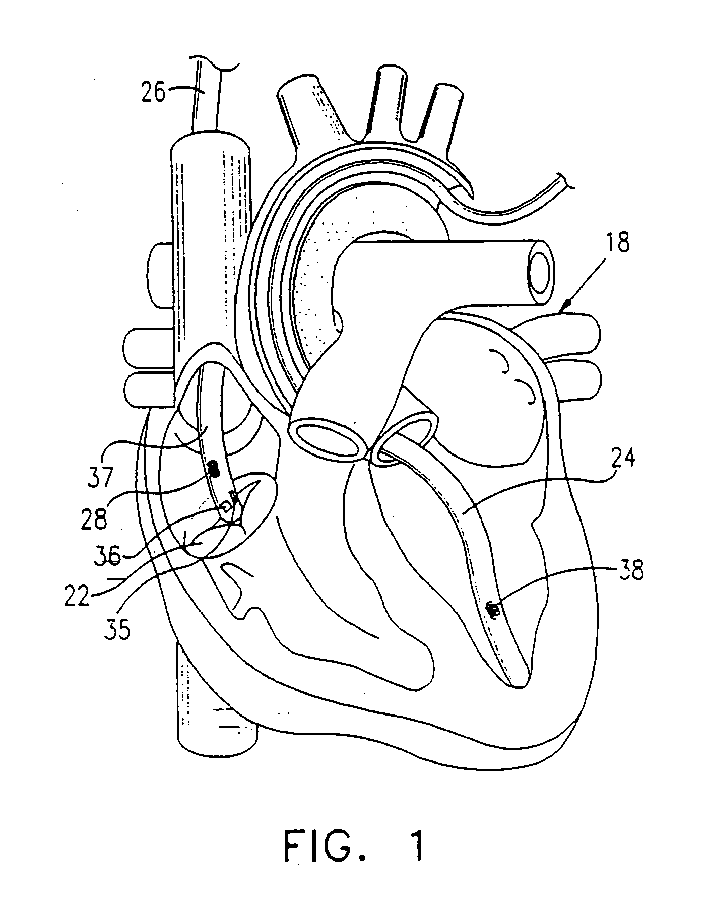
[0086]FIG. 1 shows a patient's heart 18 with a tricuspid valve 22 therein, which is measured in accordance with a preferred embodiment of the present invention. A measurement catheter 26 is situated within the patient's heart near valve 22. A reference catheter 24, comprising a position sensor 38, is situated at a fixed point relative to heart 18, preferably at the apex thereof, such that the movements of catheter 24 coincide with the movements of heart 18.

[0087] Catheter 26 is preferably thin and durable and is suitable for insertion into and maneuvering within the patient's heart. Such catheters are described, for example, in PCT patent application US95 / 01103 and in U.S. Pat. Nos. 5,404,297, 5,368,592, 5,431,168, 5,383,923, the disclosures of which are incorporated herein by reference. Preferably, catheter 26 comprises a pressure sensor 36, at least one position sensor 28, and one or more working channels 37 which allow attachment of catheter 26 by suction to points within heart ...


PUM


Abstract

A method of measuring the size of an area (22) within a body, including bringing at least one position sensor (28) to each of a plurality of points in the area, determining position coordinates of the plurality of points, using the sensor (28) and calculating distances between the plurality of points.

Description

RELATED APPLICATIONS [0001] This application is a Continuation-in-Part of U.S. patent application Ser. No. 08 / 595,365, which is assigned to the assignee of the present patent application and whose disclosure is incorporated herein by reference.FIELD OF THE INVENTION [0002] The present invention relates generally to the field of intrabody position determination, and specifically to intrabody measurements using position determination. BACKGROUND OF THE INVENTION [0003] There are many cases in which it is desired to measure organs or spaces within a patient's body. One such case is in preparation for organ transplantation. In transplantation procedures, in order to speed up the transplantation procedure and minimize the period in which the patient is without the transplanted organ, the new organ is preferably prepared before the transplantation procedure. In order to ensure proper reception of the new organ, it must be as similar as possible to the organ that is removed. In some organs...

Claims


Application Information

Patent Timeline
Patent Type & Authority Applications(United States)
IPC IPC(8): A61B5/00A61B5/0215A61B5/029A61B5/042A61B5/05A61B5/06A61B5/107A61B17/00A61B18/20A61N1/32A61N1/362A61N1/365A61N1/368
CPCA61B5/0215A61N1/368A61B5/0422A61B5/06A61B5/1076A61B5/1077A61B5/145A61B5/4504A61B5/6843A61B5/6885A61B18/20A61B2017/00247A61B2018/00392A61N1/32A61N1/3627A61N1/36564A61B5/029A61B5/062A61B5/287Y10S623/912
Inventor BEN-HAIM, SHLOMOFENSTER, MAIER
Owner BEN HAIM SHLOMO
Why Eureka
Try Eureka