Stereoscopic imaging assembly employing a flat panel display

a stereoscopic imaging and flat panel display technology, applied in the field of stereoscopic imaging, can solve the problems of not being easily adaptable to visual navigation applications for vehicles with severe space constraints, affecting the accuracy of stereoscopic imaging, so as to eliminate half-black imaging and reduce the parallax of the first and second polarized images

Inactive Publication Date: 2007-09-25
L 3 COMM CORP
View PDF6 Cites 4 Cited by
  • Summary
  • Abstract
  • Description
  • Claims
  • Application Information

AI Technical Summary

Benefits of technology

[0014]In accordance with another preferred embodiment, the display further includes means for substantially eliminating half-black imaging received by the first and second eyes. In accordance with a number of still different preferred embodiments, the display further includes a backlight source, a front plate, a diffuser, and / or an integrator. When the backlight source is present, the rear polarizer is preferably positioned between the backlight source and the first and second image pixels. When the front plate is present, the front polarizer is preferably positioned between the front plate and the first and second image pixels. When the diffuser is present, the front polarizer is preferably positioned between the diffuser and the first and second image pixels. When the integrator is present, the front polarizer is preferably positioned between the integrator and the first and second image pixels.
[0021]In accordance with a preferred embodiment, the method further comprises the observer synthesizing the first and second polarized images into a stereoscopic visual image. The method also further comprises, providing a viewing panel to visually display the first and second polarized to the observer. The first and second polarized images are more preferably continuously displayed on the viewing panel and parallax of the first and second polarized images is substantially diminished. The first polarized image preferably simultaneously fills an entirety of the viewing panel, while the second polarized image fills the entirety of the viewing panel to substantially eliminate half-black imaging received by the first and second eyes.

Problems solved by technology

One of the shortcomings of conventional optical navigation systems is that the two-dimensional images produced by the displays lack a sensation of depth, which can lead to operator disorientation and navigational errors with serious consequences, particularly in combat situations.
Although stereoscopic imaging technology, which produces so called 3-D stereo images, i.e., two-dimensional images having a sensation of depth, has been in existence for many years, prior art stereoscopic imaging technology is not readily adaptable to visual navigation applications for vehicles having severe space constraints, which is typical of most land-based military vehicles.
Prior art stereoscopic imaging assemblies generally employ CRT displays, which are effective for their intended purpose, but are relatively cumbersome.
Size constraints make CRT displays prohibitively bulky for most military applications as well as many civilian applications.
Flat panel displays can meet the size constraints for military applications, but to date have not met the performance requirements for stereoscopic imaging assemblies.

Method used


Image

  • Stereoscopic imaging assembly employing a flat panel display
  • Stereoscopic imaging assembly employing a flat panel display
  • Stereoscopic imaging assembly employing a flat panel display

Examples


Embodiment Construction

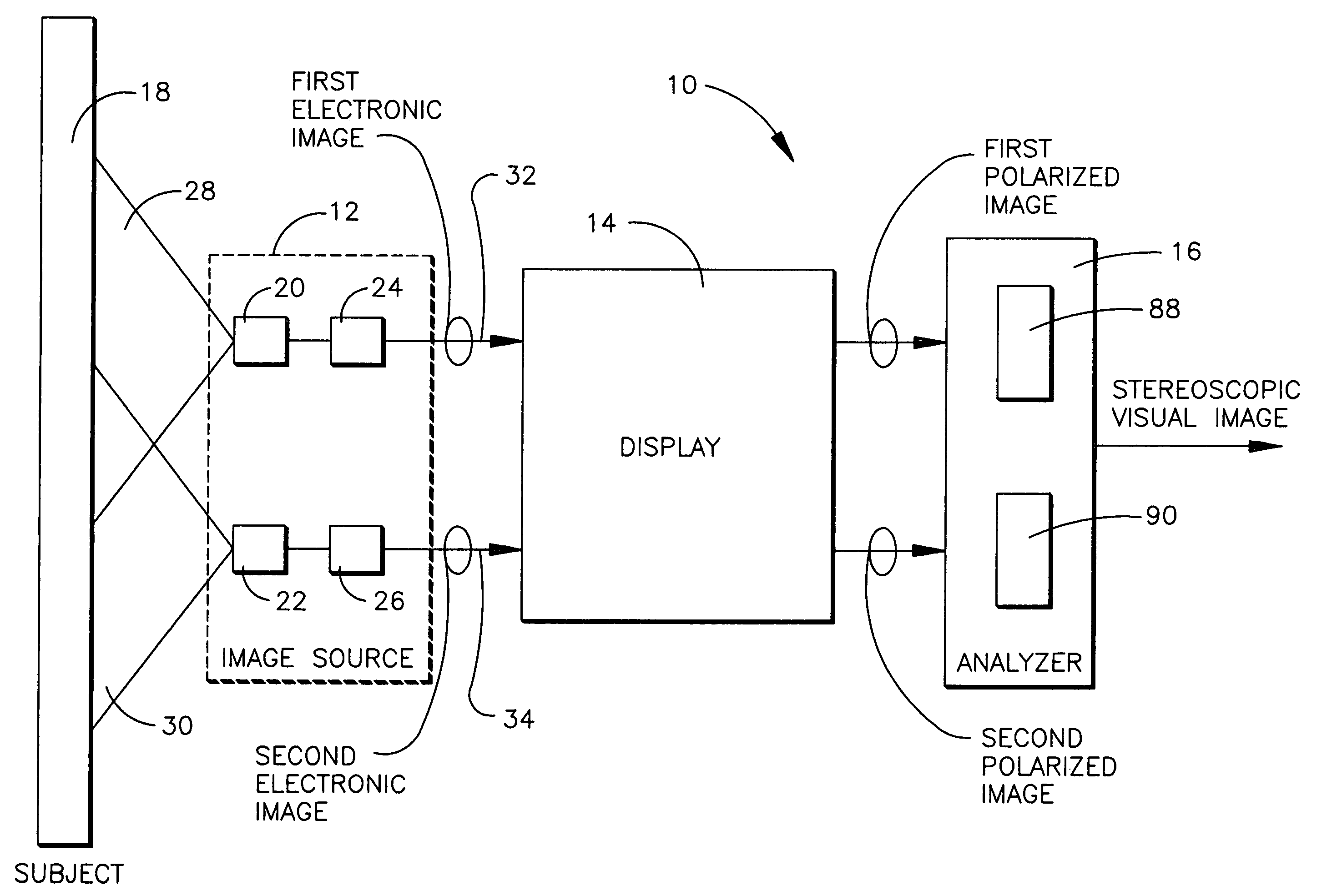
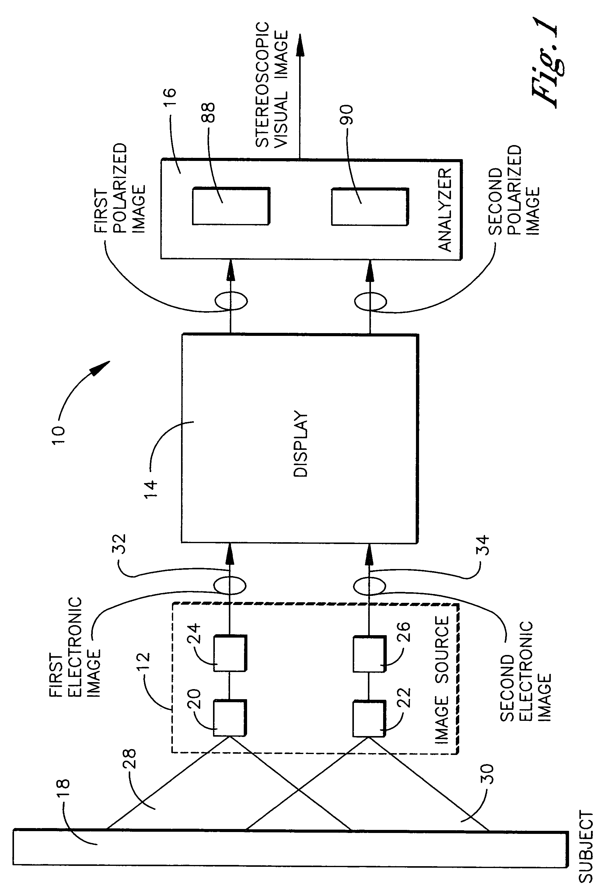
[0029]Referring to FIG. 1, an embodiment of the stereoscopic imaging assembly of the present invention is shown and generally designated 10. The stereoscopic imaging assembly 10 has a plurality of components functioning in series along an image pathway, which extends from an image source to an analyzer. In particular, the stereoscopic imaging assembly 10 comprises an image source 12, a display 14, and an analyzer 16. The stereoscopic imaging assembly 10 has general utility to essentially any application which requires or benefits from the conversion of a true visual image of a subject 18 to a stereoscopic visual image of the subject 18 for viewing by a person having visual access to the display 14 and analyzer 16, but not necessarily to the subject 18. The stereoscopic imaging assembly 10 is described below in the context of a specific application, i.e., visual navigation of a vehicle, for purposes of illustrating a preferred embodiment of the stereoscopic imaging assembly 10. Howev...


PUM

PropertyMeasurementUnit
thicknessaaaaaaaaaa
sizeaaaaaaaaaa
sizeaaaaaaaaaa

Abstract

A stereoscopic imaging assembly for converting true visual images of a real-life subject to a stereoscopic image includes a display and an analyzer. The display is preferably a liquid crystal display, which includes first image pixels, second image pixels, and a polarizer. The first image pixels are responsive to a first electronic image of a first true visual image and the second image pixels are responsive to a second electronic image of a second true visual image. The polarizer has a first polarization material, which enables transmission of light of a first polarity, while blocking light of a second polarity, thereby transmitting a first polarized image having a first polarity. A second polarization material enables transmission of light of the second polarity, while blocking light of the first polarity, thereby transmitting a second polarized image having a second polarity. The analyzer delivers the first polarized image to the first eye of an observer while excluding the second and delivers the second polarized image to the second eye while excluding the first, which enables the observer to synthesize the first and second polarized images into a stereoscopic visual image.

Description

[0001]This is a non-provisional patent application claiming the benefit of my Provisional Patent Application No. 60 / 509,812, filed on Oct. 8, 2003, and entitled “Stereoscopic Imaging Assembly Employing a Flat Panel Display”, which is incorporated herein by reference.TECHNICAL FIELD[0002]The present invention relates generally to stereoscopic imaging, and more particularly to a stereoscopic imaging assembly which includes a flat panel display and an associated analyzer.BACKGROUND OF THE INVENTION[0003]Many land-based military vehicles, particularly armored vehicles, such as tanks, personnel carriers, and the like, are provided with optical navigation systems, which enable the vehicle operator to visually navigate the vehicle while the operator resides in the interior of the vehicle in visual isolation from the surroundings of the vehicle. The operator navigates the vehicle by viewing a display for the optical navigation system, which provides the operator with a two-dimensional liken...

Claims


Application Information

Patent Timeline
Patent Type & Authority Patents(United States)
IPC IPC(8): G02F1/1335G02B30/25
CPCG02B27/26G02B30/25
Inventor BLANCHARD, RANDALL D.
Owner L 3 COMM CORP
Why Eureka
Try Eureka