Stackable network units with resiliency facility

a technology of network units and storage units, applied in the field of storage units, can solve problems such as ambiguous situations for any devi

Active Publication Date: 2007-09-25
HEWLETT-PACKARD ENTERPRISE DEV LP +1
View PDF14 Cites 19 Cited by
  • Summary
  • Abstract
  • Description
  • Claims
  • Application Information

AI Technical Summary

Benefits of technology

[0010]The present invention in a preferred form allows the units of a stack to operate in the following manner in the event of a ‘splitting’ of the stack into two or more segments. One of those segments would include the master unit: that segment preferably continues to operate uninterrupted. A separated segment comprising one or more none of which is the original master will elect a new (potential) master. This potential master will listen for the existence of another master broadcasting its existence (preferably by means of the discovery protocol message mentioned above) so that if the other (original) master is detected routing will be disabled for the ‘separated’ segment.
[0011]If a stack splits and there is no connectivity between the segments each segment will act as a router for identical interfaces. Should connectivity be re-established between the previously disconnected segments, the masters of the respective segments preferably negotiate to determine which of them will be the single master for the reconnected stack and which therefore will control the routing interfaces.

Problems solved by technology

In the event of such a failure, if units in both ‘halves’ or segments of the stack continue to provide full functional capability, such as for example full routing functionality, then two such units may exist on potentially the same network with the same identity, causing an ambiguous situation for any device wishing to communicate through them.

Method used


Image

  • Stackable network units with resiliency facility
  • Stackable network units with resiliency facility
  • Stackable network units with resiliency facility

Examples


Embodiment Construction

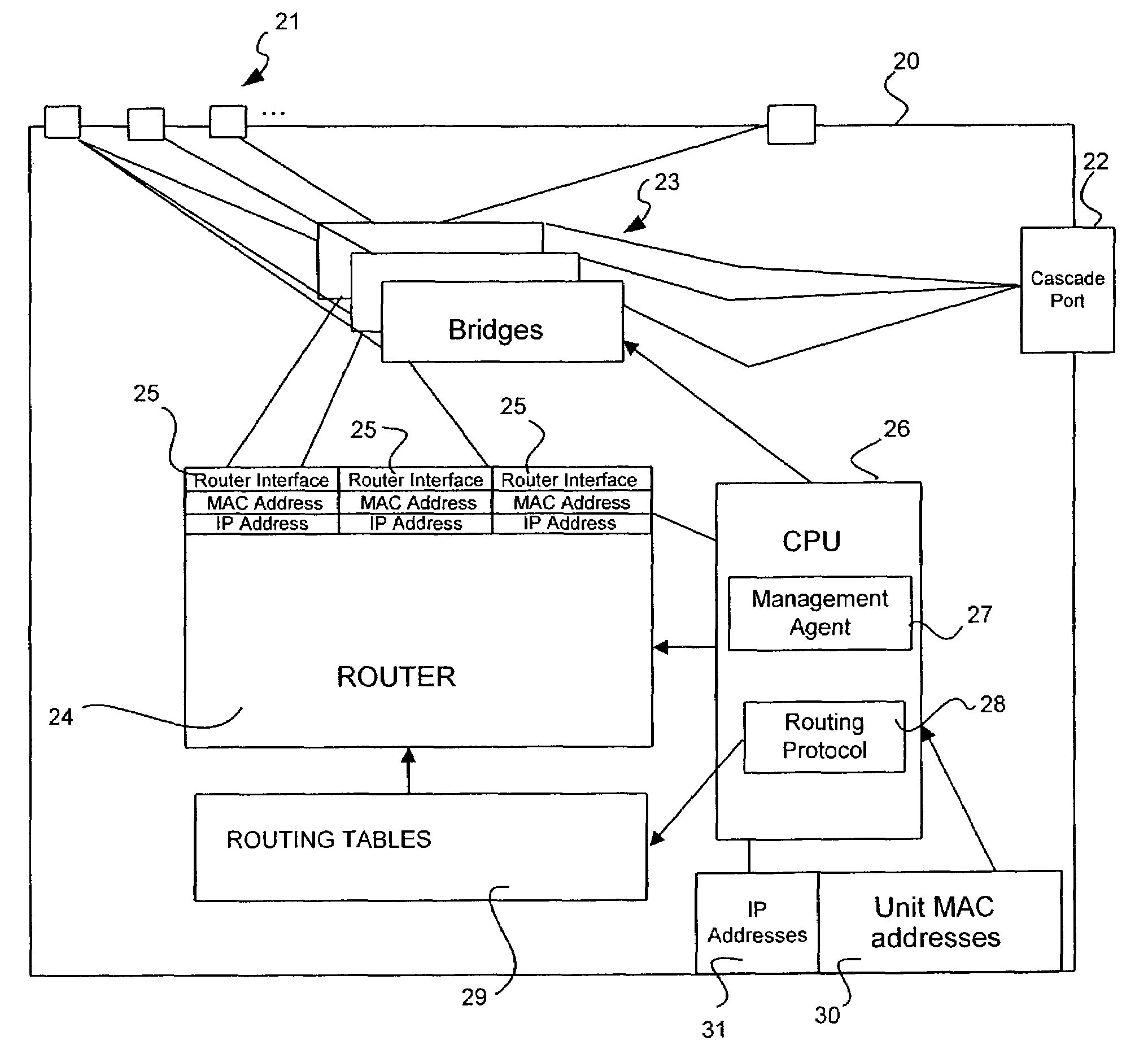
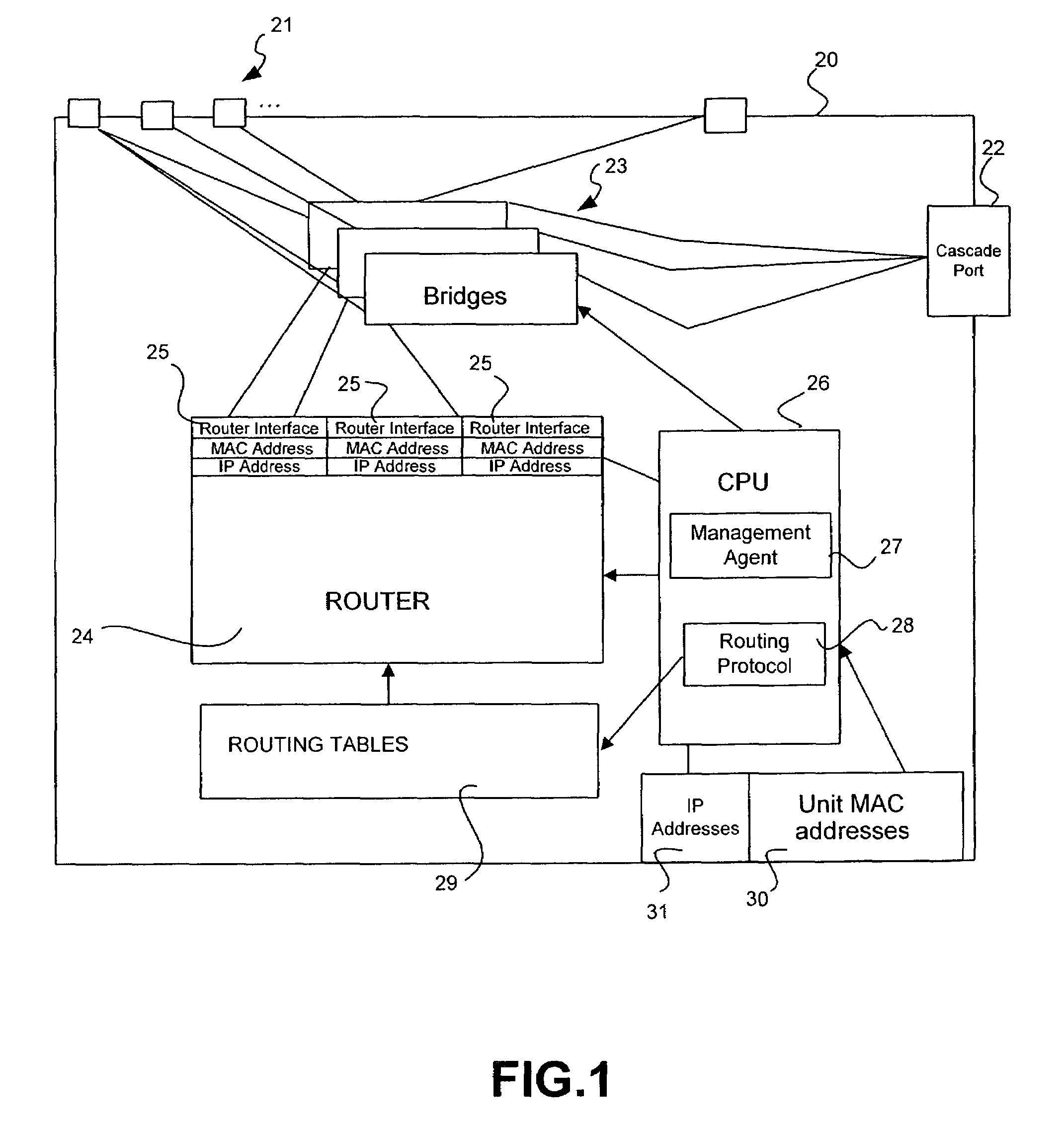
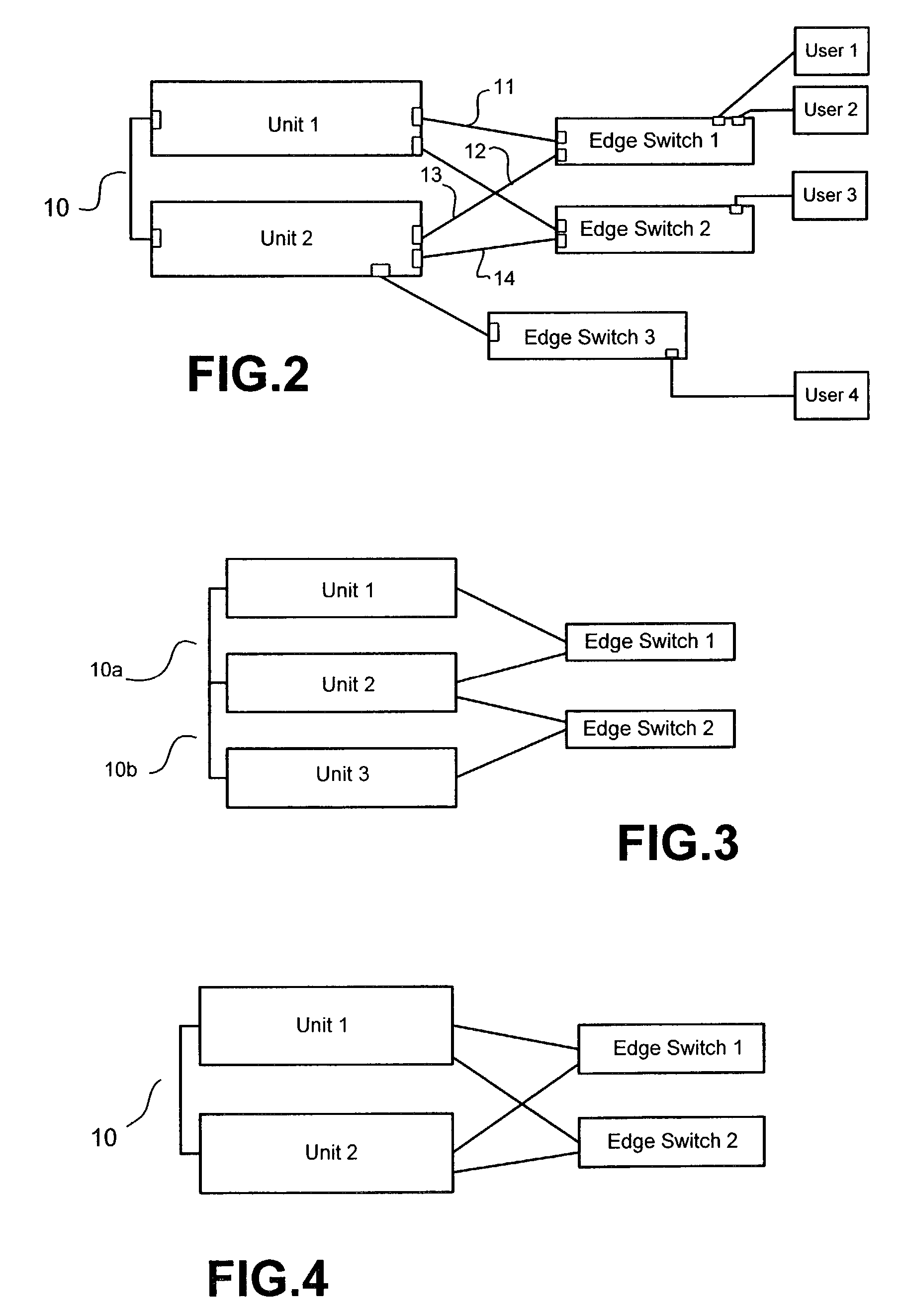
[0021]FIG. 1 illustrates, in conjunction with FIG. 6 to be described later, a network unit in accordance with the invention and which is to be used in a cascaded stack according, for example, to the schemes shown in FIGS. 2 to 5.

[0022]The unit 20 has a multiplicity of ordinary or ‘front panel’ ports 21 and at least one cascade port 22 The unit includes at least one and usually a multiplicity of ‘hardware’ bridges, or ‘layer 2’ switches 23. Each port 21 is connected to at least one of the bridges 23 and the (or each) cascade port is connected to all the bridges, or to a ‘logical’ port connected to all the bridges. The unit includes a router 24 which has at least two, and in the illustrated example three, router interfaces 25. Each router interface 25 is connected to one bridge only, although each bridge may be connected to more than one router interface 25. For each interface there is some means such as a register storing a MAC address and a network (IP) address for the interface. Fo...


PUM


Abstract

A network unit comprises a multiplicity of ports for transmitting and receiving data packets, a bridging facility and a routing facility. The network unit has a multiplicity of mutually exclusive states which includes an initial state from which said network unit can transition to either a slave state; or a waiting state from which in the absence of receipt from elsewhere of a broadcast advertisement including an advertised address corresponding to an address of the unit, the unit transitions to a master routing state in which the routing facility is enabled and the unit broadcasts a corresponding advertisement including an address of the unit. The unit transitions from the waiting state, when it receives from elsewhere (i.e., another unit) such a broadcast advertisement, to a master bridging state in which the routing facility is disabled and the unit provides commands for disabling a routing facility of other similar units to which the network is connected. The states include a slave routing state, in which the routing facility is enabled, and a slave bridging state, in which the routing facility is disabled. In the slave states the advertisements are not broadcast and the unit responds to routing enabling and disabling commands from a unit in a master state. The scheme provides in conjunction with external connectivity resilience in the event of a cascade failure.

Description

REFERENCE TO RELATED APPLICATION[0001]This application claims the priority of U.S. provisional application No. 60 / 363,046 filed Mar. 11, 2002. The contents thereof are hereby incorporated by reference.FIELD OF THE INVENTION[0002]This invention relates generally to packet-based communication networks and more particularly to network units, such as units capable of routing and bridging, which are stackable to constitute a single network entity. More particularly the invention relates to the provision of ‘resilience’ to allow the units in a stack, or remaining units in a stack, to continue to operate notwithstanding the failure of a cascade connection between the units of the stack.BACKGROUND TO THE INVENTION[0003]Network units such as switches and routers which include a multiplicity of ports for connection to other units or users are commonly made with a fixed number of ports in order to achieve efficiency of manufacture. It is known to ‘stack’ such units, by which is meant their con...

Claims


Application Information

Patent Timeline
Patent Type & Authority Patents(United States)
IPC IPC(8): H04L12/28H04L12/56
CPCH04L45/02H04L45/16H04L45/583
Inventor WEYMAN, RAPHAEL JAQUINO, FRANCISCOREINAUER, DAVIDTULACZ, JACEK ARIEGEL, JANE A
Owner HEWLETT-PACKARD ENTERPRISE DEV LP
Why Eureka
Try Eureka