Key switch with at least one switching position

a technology of key switch and switching position, which is applied in the field of key switch, can solve the problems of increasing the complexity of the lock, and reducing the number of desired switching states, and resulting in extremely complex and wasteful effects

Inactive Publication Date: 2007-10-02
SIEMENS AG
View PDF14 Cites 7 Cited by
  • Summary
  • Abstract
  • Description
  • Claims
  • Application Information

AI Technical Summary

Benefits of technology

[0008]From the document EP 0 483 048 B1 an automotive ignition switch with a “key-in-warning” safety switch inner to the ignition switch is known. The said ignition switch does not require the necessity of an independent switch for the “key-in-ignition” warning circuit. Both switching circuits are integrated into each other and therefore one less mounting to design, translates into a saving in both material and design cost.
[0020]Another advantage results from the fact that the switching positions, which correspond to certain switching states, can be visually detected from the key position in the lock. Furthermore it is possible to use more than one pin rows or pin arrangements or at least partly divided pins, in order to allow key hierarchies. Hence the key switch represents a technically elegant, user-friendly, cost-effective and safe solution for key switch applications in many scenarios.

Problems solved by technology

For every key position enabled for key withdrawal another set of pin row(s) is required, which increases complexity of the lock.
Unfortunately, the complexity scales with the number of desired switching states.
A key switch based on the known technology combining a hierarchical locking system with the option to withdraw the key from multiple key positions is consequently extremely complex and wasteful.
If both features are to be combined the user has to accept major drawbacks which result in reduced functional security or substantial inconveniencies during use.
However, this system would require a high number of mechanical parts and increases substantially in dimension.
As a matter of fact, such a system would become extremely complex and costly.

Method used


Image

  • Key switch with at least one switching position
  • Key switch with at least one switching position
  • Key switch with at least one switching position

Examples


Embodiment Construction

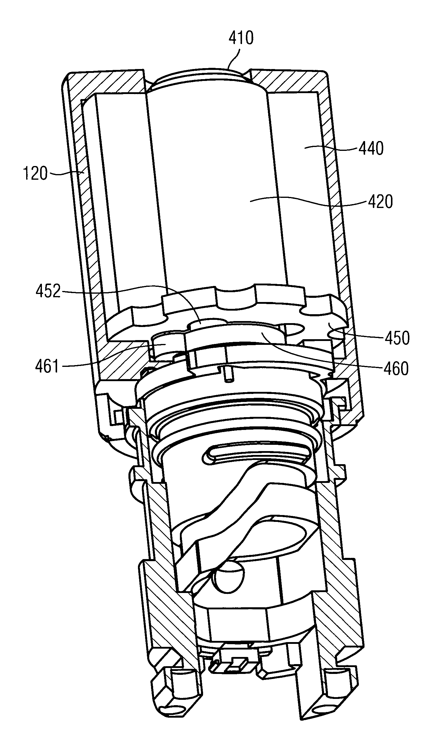
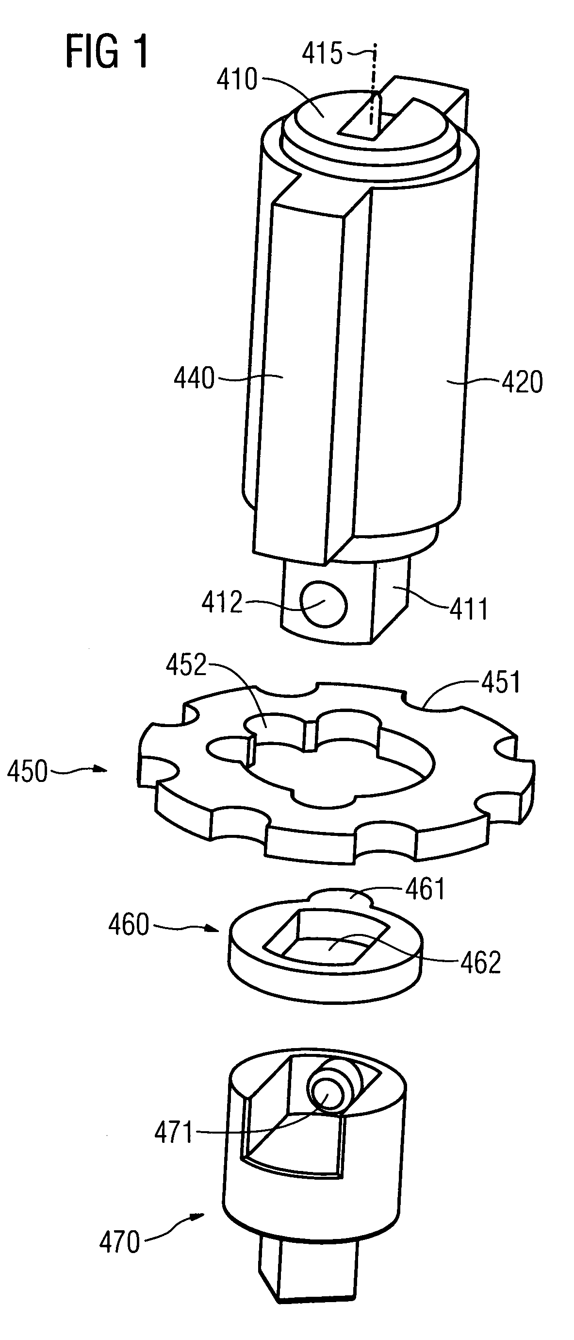
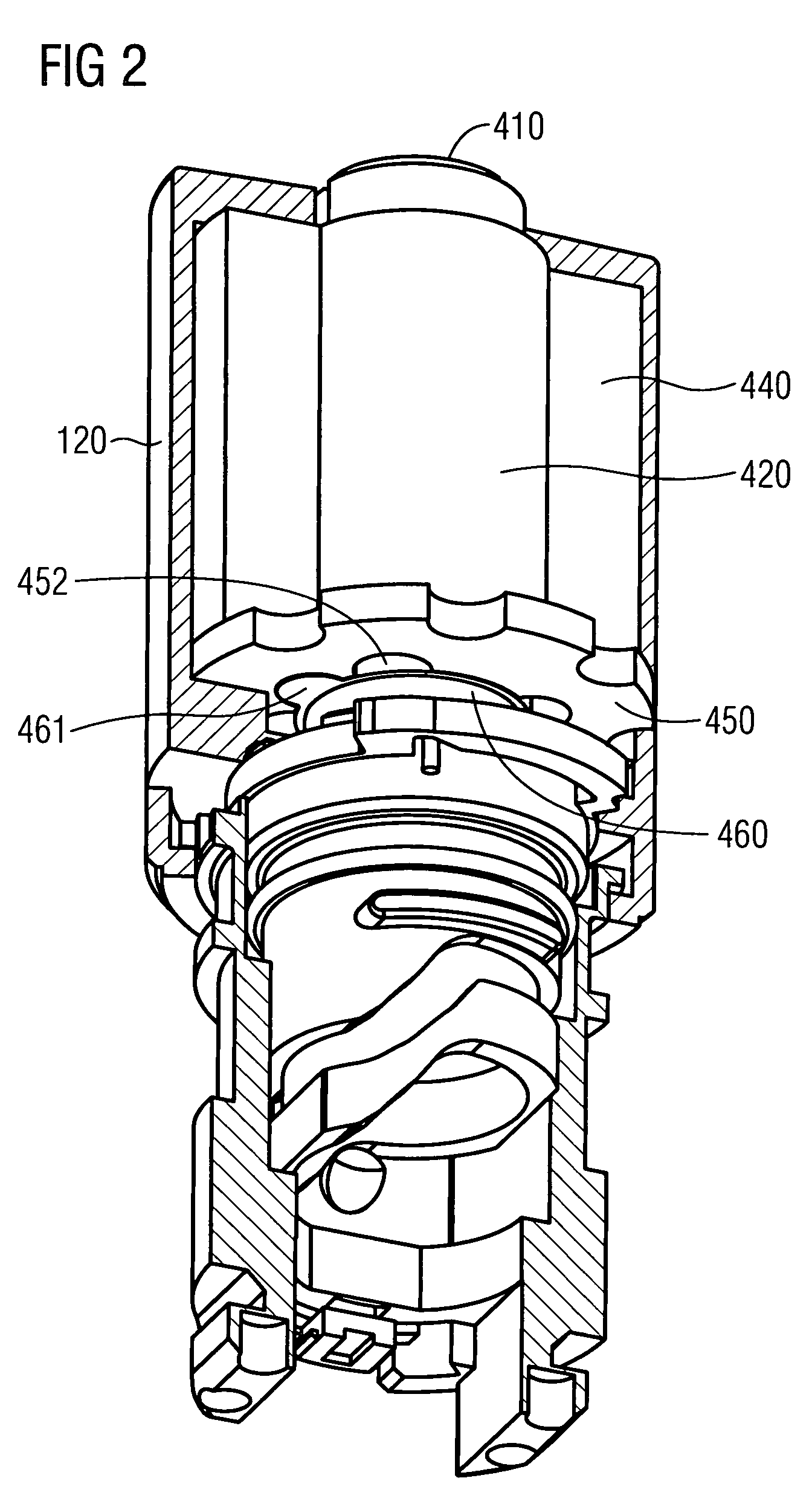
[0027]FIG. 1 is a view of disassembled essential parts of a key switch. The essential parts of the key switch are located along the rotational axis 415. The essential parts are the cylindrical lock 410 being located inside the lock holder 420, the first washer 450, the second washer 460 and an adapter 470. The joint linear translation of the cylindrical lock 410, the second washer 460 and the adapter 470 are designed to be form-locking for rotations as well as linear translations. The cylindrical lock 410 slides linearly inside the lock holder 420 and is connected to the adapter 470 using a hole 412 to be engaged into the bolt 471 of the adapter 470. The second washer 460 is designed to be placed onto the extremity 411 of the cylindrical lock 410. Furthermore is the clearing 462 of the second washer 460 designed to be form-locking upon rotation around the rotational axis 415. When assembled the adapter 470 is engaged with the extremity 411 and its bolt 471 is inserted inside the hol...


PUM


Abstract

The invention relates to a key switch with at least one turn-key switching position comprising a cylindrical lock adapted to perform a translation upon key authorization. The aim is to present a key switch being capable of allowing key hierarchies as well as the withdrawal of the key in particular switching positions. For this purpose the key switch also comprises a lock holder adapted to host the translation of a cylindrical lock in respect to the lock holder along a common rotational axis and the cylindrical lock being form-locking with the lock holder for rotations around the rotational axis. The user is able to employ the turning key movement for the selection of a switching position and an outward and inward linear translation of the key to lock or unlock a switching position.

Description

FIELD OF THE INVENTION[0001]The invention relates to a key switch with at least one switching position comprising a cylindrical lock adapted to perform a translation upon key authorization.BACKGROUND OF THE INVENTION[0002]The above described type of key switch finds manifold applications in combination with control and switching devices.[0003]Several of these applications may be found in the industrial and the private sector. In general the control or switching device has an authorization mechanism based on a key lock. Possible private applications are key switches to authorize a closing and opening of automated garage doors or the enabling or disabling of the elevator service for certain floors of a building, for example. Possible industrial applications are, for example, control and switching devices as integrated units of machines or production lines.SUMMARY OF THE INVENTION[0004]In most of the mentioned applications it is favorable to assign a number of key positions to the resp...

Claims


Application Information

Patent Timeline
Patent Type & Authority Patents(United States)
IPC IPC(8): E05B17/04E05B27/00
CPCH01H27/06Y10T70/7949Y10T70/7706Y10T70/7576Y10T70/7712
Inventor ZIMMERMAN, RUDOLF
Owner SIEMENS AG
Why Eureka
Try Eureka