Lock

a technology of locking mechanism and lock body, which is applied in the field of locks, can solve the problems of inability to activate the connection between the first part and the second part of the first section of the shaft, and achieve the effect of low energy consumption, simple and reliable locking mechanism actuation

Inactive Publication Date: 2007-10-02
BURG WACHTER
View PDF22 Cites 27 Cited by
  • Summary
  • Abstract
  • Description
  • Claims
  • Application Information

AI Technical Summary

Benefits of technology

[0007]Starting from this prior art the invention is based on the problem of developing a lock of this type in such a way that it can be used for various applications as a result of its construction design, in particular with a standard locking cylinder in various doors and that it allows, in particular, a simple, reliable, low-energy actuation of the locking mechanism.

Problems solved by technology

Any active connection between the first part and the second part of the first section of the shaft will not be possible then.

Method used


Image

  • Lock
  • Lock
  • Lock

Examples


Embodiment Construction

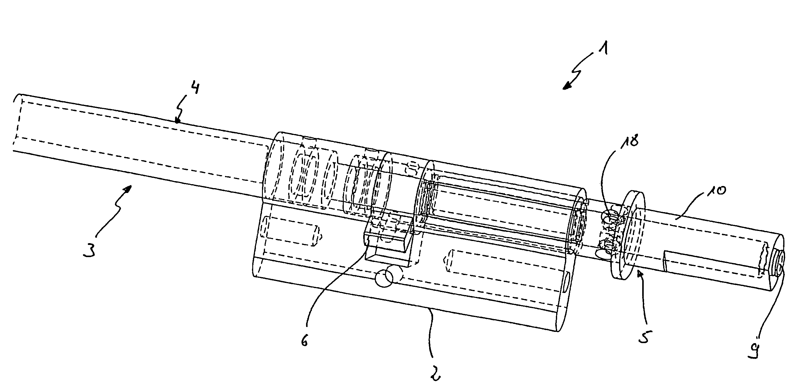
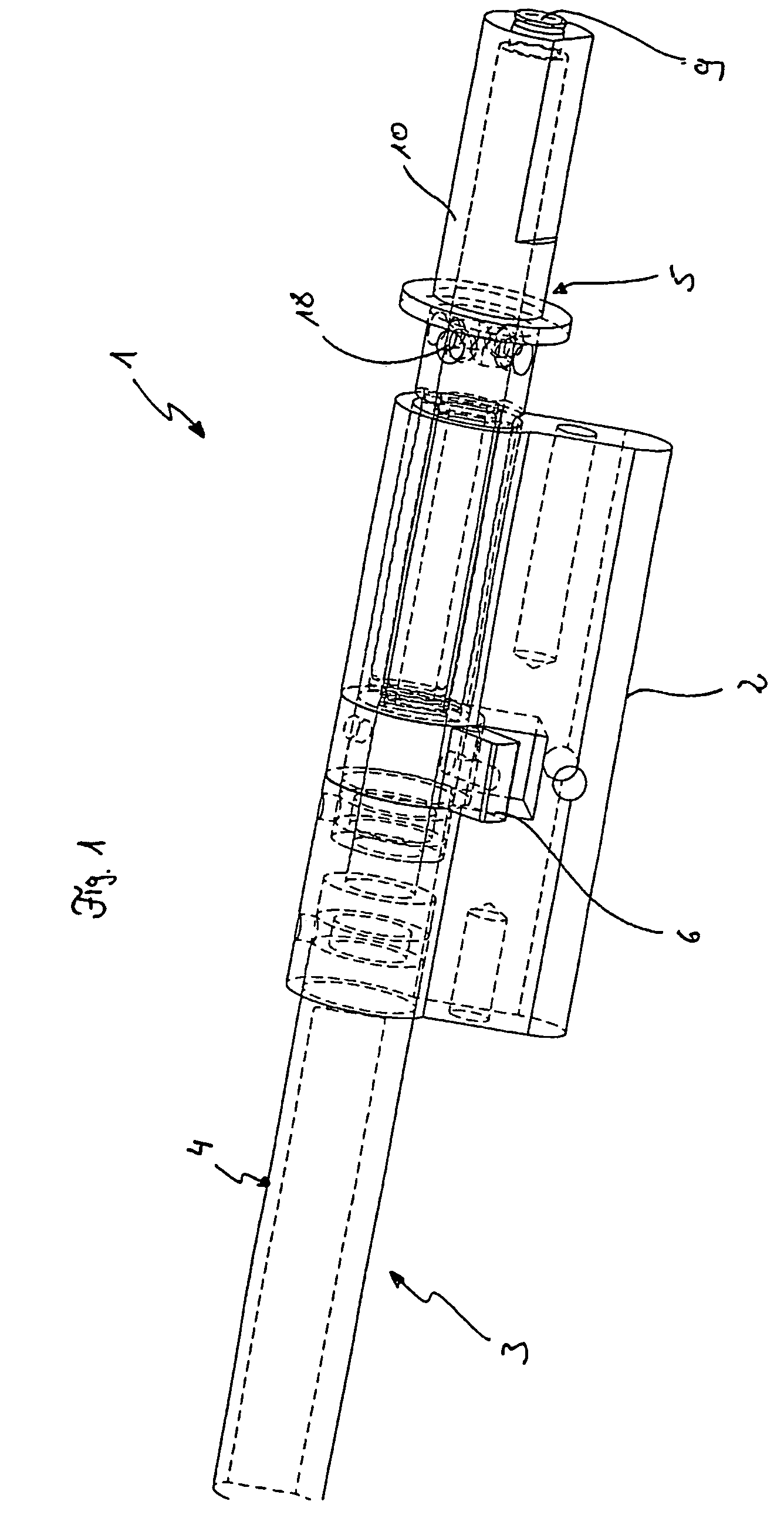
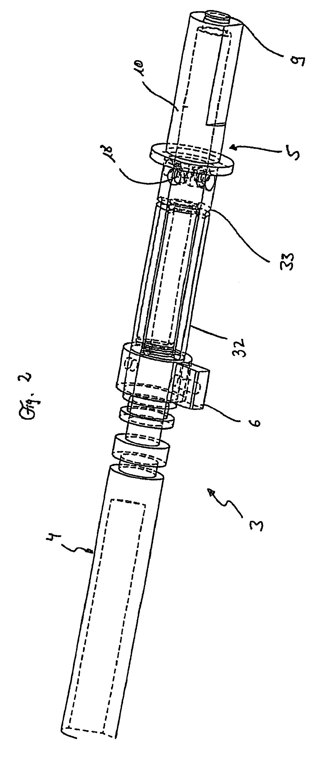
[0047]A lock as represented in the FIGS. 1 to 6 is formed as a mortise lock for installation in a door leaf and includes a locking cylinder 2 that is fixed in the door leaf which is not further shown. The locking cylinder 2 is penetrated by a shaft 3 that is formed of two sections 4 and 5.

[0048]Rotary knobs (not shown in FIG. 1) are fixed for rotation with the ends of these sections 4 and 5, by means of which rotary knobs a locking nose 6 of the cylinder 2 mounted on shaft 3 can be pivoted if necessary upon recognition of an authorisation code that unlocks the lock 1.

[0049]The above-mentioned rotary knobs are shown in FIG. 4 and are designated by reference numbers 7 and 8. FIG. 4, to which reference is made in the following, also shows a basic diagram of the shaft 3.

[0050]The section 5 of shaft 3 is formed in two parts and includes two coaxially arranged parts 9 and 10, of which the first part 9 is coaxially arranged for rotation in the second part 10 of the first section 5 of shaft...


PUM


Abstract

A lock, such as a mortise lock, for a door. The lock comprises a locking cylinder that can be inserted into a door leaf and a shaft having two sections, each section of the shaft having a handle at the end, preferably a rotary knob or a standard door handle and being actively interconnected by a coupling after recognition of an authorisation code. The lock can be used for various applications as a result of its construction design, with a standard locking cylinder in various doors and that it allows, a simple, reliable, low-energy actuation of the locking mechanism. To achieve this, the coupling (11) comprises at least two, preferably four or more rolling members (17) that are guided in recesses (18) of a second part (10) of a first section (5) of the shaft (3). The rolling members can be pushed into cavities (20) that run around the periphery of the first part (9) of the first section (5) of the shaft (3), in order to actively connect a first part (9) and the second part (10) of the first section (5) of the shaft (3), using a radially or axially displaceable sliding element (22).

Description

BACKGROUND[0001]1. Field of the Invention[0002]This invention relates to a lock, in particular a mortise lock for a door. Said lock comprises a locking cylinder that can in particular be inserted into a door leaf and a shaft consisting of two sections, each section of said shaft having a handle at the end, preferably a rotary knob or a standard door handle, and being actively interconnected by means of a coupling after recognition of an authorisation code.[0003]2. Description of Related Art[0004]Locks of this kind are known from prior art. They are built into door leafs particularly in the entrance door area, the opening and closing of the door, i.e. the movement of a catch bolt being accomplished via the shaft. To this end, said shaft includes an outside door handle, in particular a freely rotatable rotary knob that allows the catch bolt to be actuated only upon prior verification of an authorisation code through the locking cylinder. On the inside of the door there is also provide...

Claims


Application Information

Patent Timeline
Patent Type & Authority Patents(United States)
IPC IPC(8): E05B13/00E05B65/08E05B47/00E05B47/06E05B49/00
CPCE05B47/0615E05B47/0649E05B47/0692E05B47/0012E05B2047/0091E05B2047/0016E05B2047/0017E05B2047/0031E05B63/006Y10T70/5416Y10T70/5823Y10T70/7102Y10T70/7107Y10T70/7751Y10T70/7949Y10T292/93
Inventor LULING, HARALDWULLNER, HERMANN-JOSEF
Owner BURG WACHTER
Why Eureka
Try Eureka