
Method and apparatus for controlling the output of a gas discharge laser system

a gas discharge laser and output control technology, which is applied in the direction of laser details, laser arrangement, active medium materials, etc., can solve the problems of providing less than acceptable performance and ineffectively using previous techniques to account for changes in gas composition over time in oscillating gas discharge lasers

Inactive Publication Date: 2007-10-02
CYMER INC +1
View PDF74 Cites 7 Cited by
  • Summary
  • Abstract
  • Description
  • Claims
  • Application Information

AI Technical Summary

Problems solved by technology

It has been found that previously used techniques for accounting for such things as the changes in the gas composition over time in oscillating gas discharge lasers are not as effective as is desirable.
This was found in practice to provide less than acceptable performance.

Method used


Image

  • Method and apparatus for controlling the output of a gas discharge laser system
  • Method and apparatus for controlling the output of a gas discharge laser system
  • Method and apparatus for controlling the output of a gas discharge laser system

Examples


Embodiment Construction

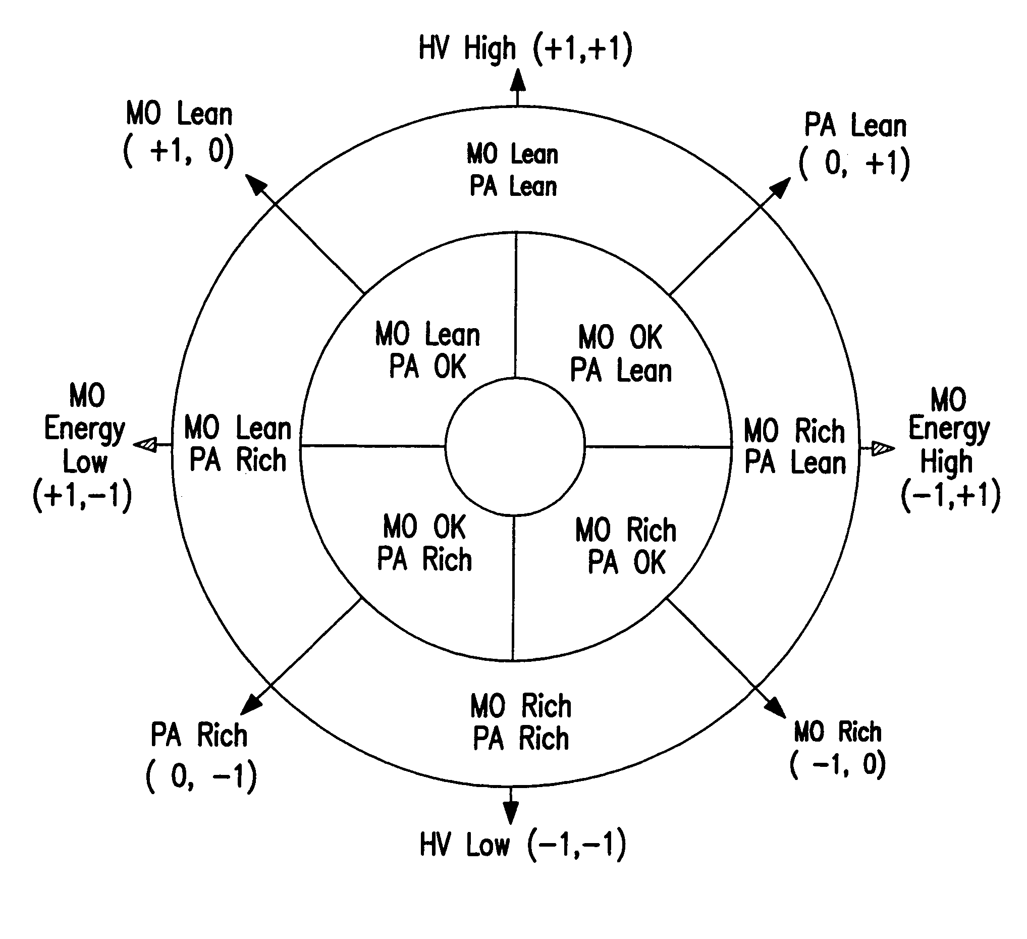
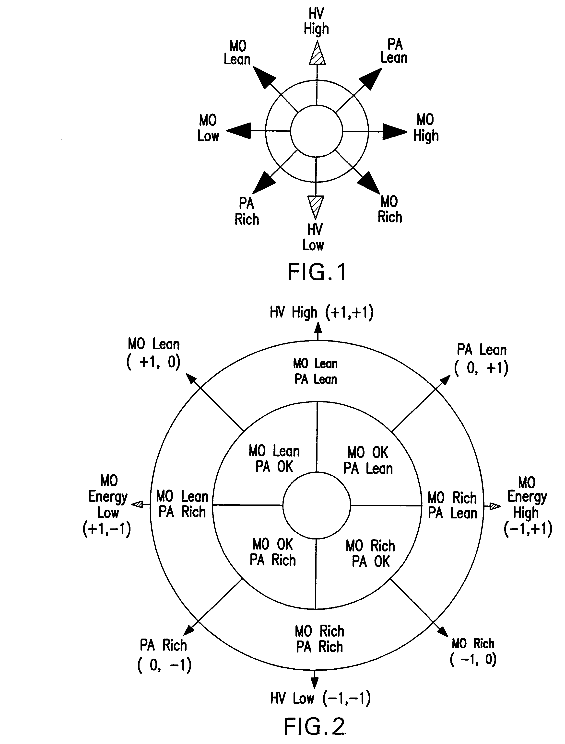
[0024]The present invention takes into account that there are a number of possible operating states the laser system could be in, given two chambers (MO, PA) and defining several gas states, e.g., three relative gas states (Lean, Good, Rich). With “good” meaning within some pre-selected target range (which may vary over the life of the laser, e.g., as changes in the electrodes, or other effects on the discharge, cause, e.g., the charging voltage on the peaking capacitors to rise in order to maintain the desired output laser light pulse beam power requirements, which are generally dictated by the end users of the light and must be met), “lean” meaning out of range with the partial pressure low, and “rich” meaning out of range with the partial pressure high. Creating a table of the nine possible combinations ([MO Good, PA Good], [MO Good, PA Lean], [MO Good, PA Rich], etc., and combining this with possible indicators of operating performance, e.g., peaking capacitor charging voltage (...


PUM


Abstract

The present invention relates to a fluorine gas discharge laser system and control of replenishment of fluorine gas as the gas discharge laser operates and consumes fluorine.

Description

RELATED APPLICATIONS[0001]This application is a continuation in part of U.S. patent application Ser. No. 10 / 740,659, filed on Dec. 18, 2003, entitled METHOD AND APPARATUS FOR CONTROLLING THE OUTPUT OF A GAS DISCHARGE MOPA LASER SYSTEM, the disclosure of which is hereby incorporated by reference.FIELD OF THE INVENTION[0002]The present invention relates to a fluorine gas discharge laser system and control of replenishment of fluorine gas as the gas discharge laser operates and consumes fluorine.BACKGROUND OF THE INVENTION[0003]Halogen based, and particularly fluorine based gas discharge lasers, e.g., KrF and ArF excimer lasers and molecular fluorine lasers are well known. They have been implemented as an oscillator, in which, e.g., a gas discharge laser, which is in a resonator cavity configuration, and with a very accurate line narrowing module or package (“LNM” or “LNP”) produces an output laser light pulse beam of pulses with a precisely defined center wavelength and a bandwidth on...

Claims


Application Information

Patent Timeline
Patent Type & Authority Patents(United States)
IPC IPC(8): H01S3/22H01S3/134H01S3/225H01S3/23
CPCH01S3/036H01S3/097H01S3/2366H01S3/134H01S3/225H01S3/10069H01S3/104H01S3/2258H01S3/2308H01S3/1306
Inventor RULE, JOHN A.ZAMBON, PAOLOWATSON, TOM A.MESINA, OMEZ S.ZHENG, WEIJIE
Owner CYMER INC
Learn More