Ballast with arc protection circuit

a protection circuit and ballast technology, applied in the direction of emergency protective arrangements for limiting excess voltage/current, energy-saving lighting, sustainable buildings, etc., can solve the problems of output arcing, high intensity, and high temperature arc generation across the air gap of ballasts

Inactive Publication Date: 2006-05-09
OSRAM SYLVANIA INC
View PDF16 Cites 50 Cited by
  • Summary
  • Abstract
  • Description
  • Claims
  • Application Information

AI Technical Summary

Problems solved by technology

As a consequence of these high ignition voltages, ballasts are subject to the problem of output arcing.
As another example, a sustained arc (as opposed to a momentary arc) arc may occur due to poor connections in the output wiring or the lamp sockets, or if a lamp is improperly installed in such a way that a small gap exists between the lamp pins and the contacts within the fixture sockets.
If a connection to the lamp(s) is compromised due to a defective lamp socket or defective wiring, a high intensity, high temperature arc may be produced across the air gap caused by these faulty conditions.
Arcing is generally acknowledged to cause degradation of the contacts in the fixture sockets and undue stress on components within the ballast.
Sustained arcing is especially undesirable because of its tendency to produce potentially destructive heating.
For instance, the normal starting process of the lamp is generally accompanied by the same types of electrical disturbances that occur during output arcing.
Thus, unless arc detection is inhibited during lamp starting, the ballast may be prevented from properly igniting the lamp.
Additionally, although most lamps are capable, under ideal conditions, of igniting and operating normally within a short period of time (e.g., 20 milliseconds), some lamps, due to age or low temperature, require a much longer time to ignite and stabilize.
Also, because lamps are somewhat unpredictable, it is possible that an otherwise “good” lamp may sometimes fail to properly start on the first attempt.

Method used


Image

  • Ballast with arc protection circuit
  • Ballast with arc protection circuit
  • Ballast with arc protection circuit

Examples


Embodiment Construction

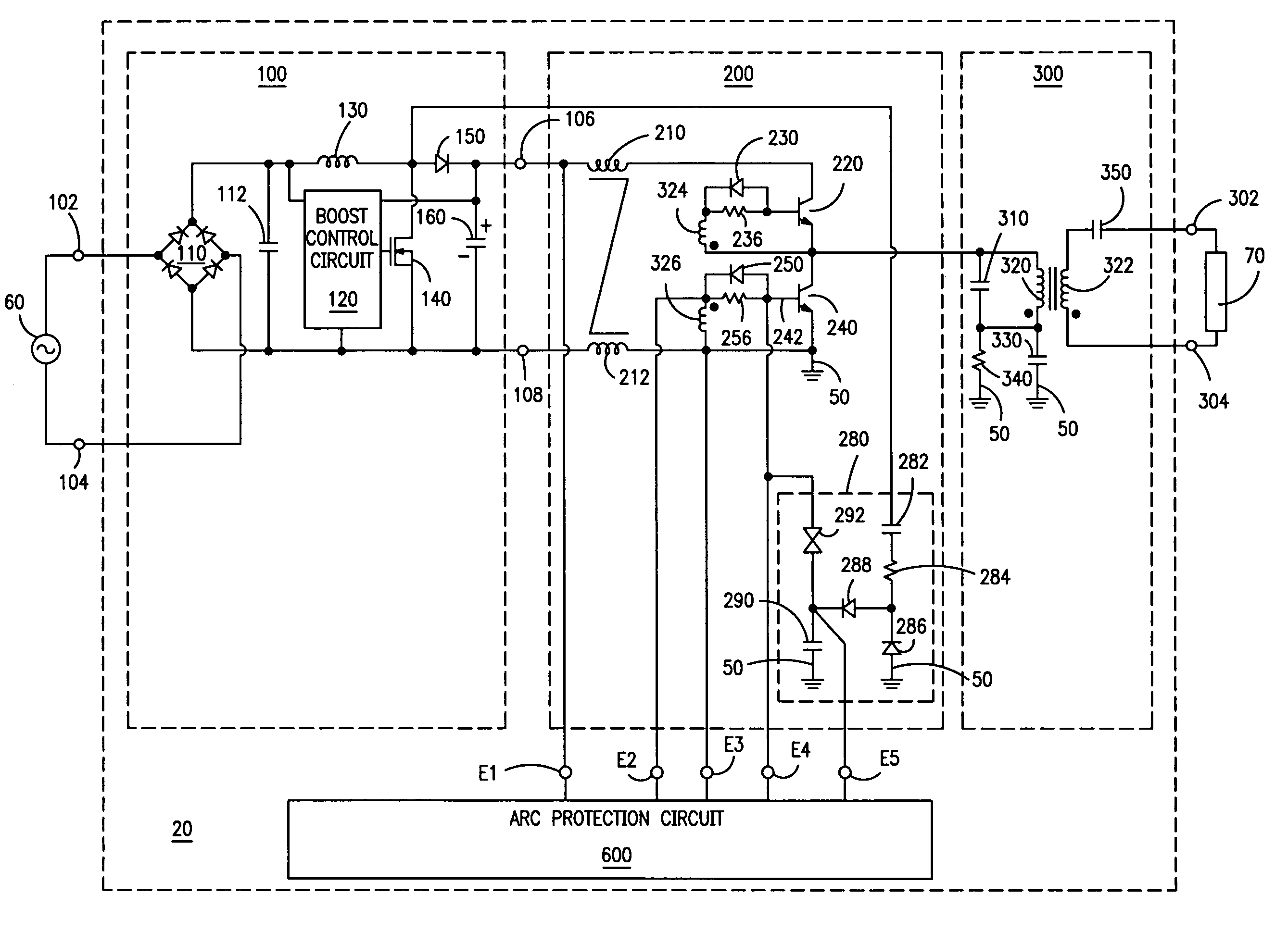
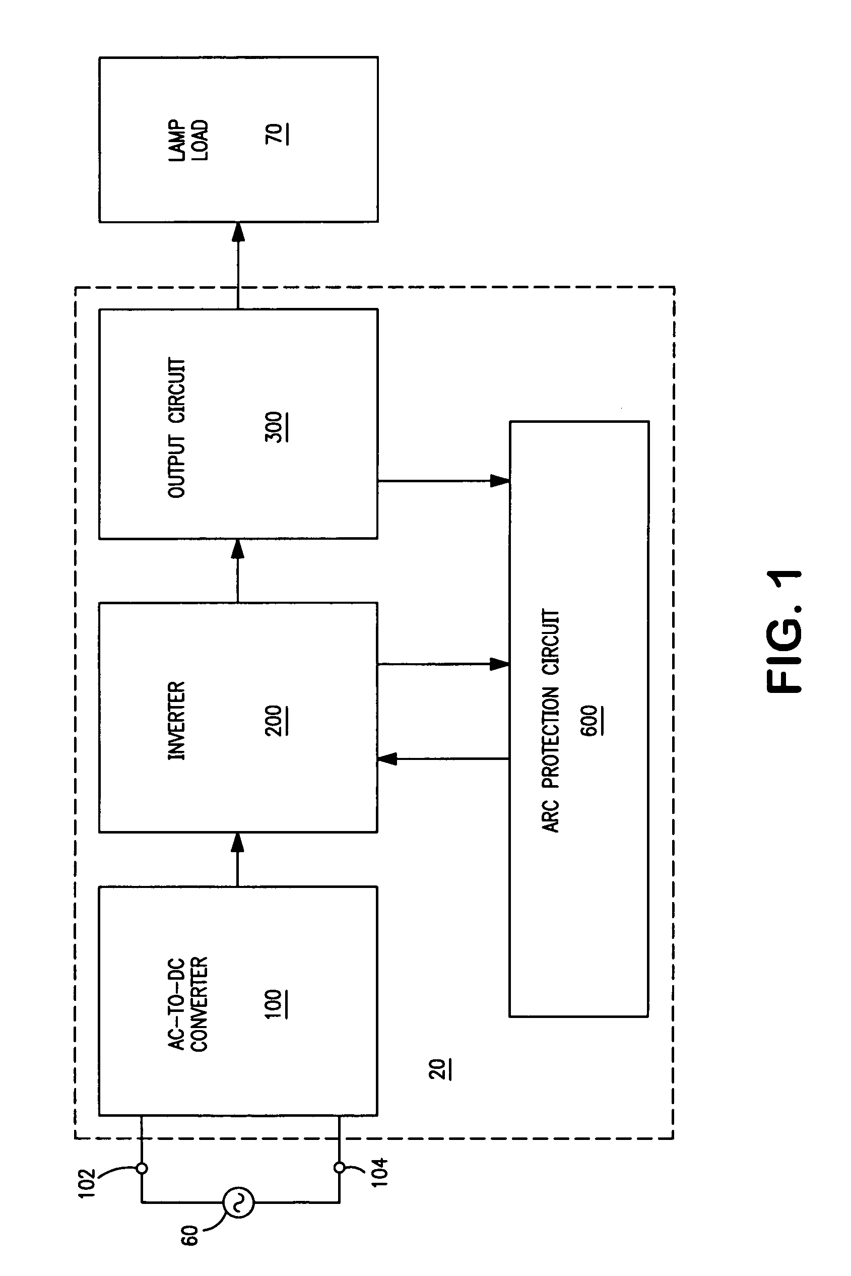
[0016]Referring to FIG. 1, a ballast 20 for powering a lamp load 70 that includes at least one gas discharge lamp comprises an AC-to-DC converter 100, an inverter 200, an output circuit 300, and an arc protection circuit 600. AC-to-DC converter 100 has an input 102,104 for receiving an AC supply voltage 60, and is operable to provide a DC rail voltage to inverter 200. Output circuit 300 is coupled to inverter 200, and is adapted for coupling to lamp load 70. Arc protection circuit 600 is coupled to inverter 200; optionally, arc protection circuit 600 is also coupled to output circuit 300.

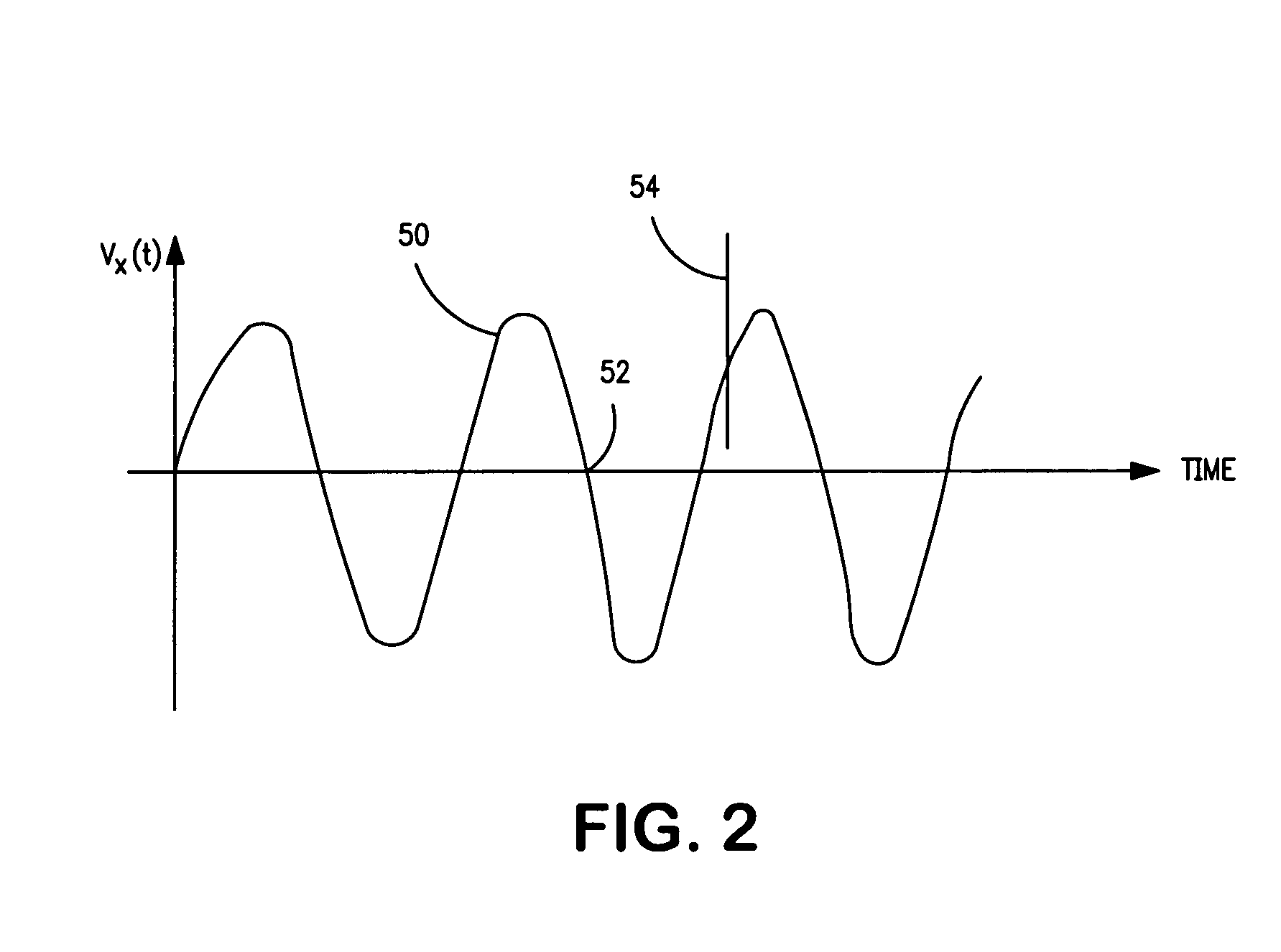
[0017]During operation, arc protection circuit 600 monitors an electrical signal within either inverter 200 or output circuit 300 for a disturbance; a disturbance is deemed to have occurred when at least a portion of the electrical signal exhibits a time-rate-of-change that exceeds a predetermined threshold value. Arc protection circuit 600 provides a timed starting period during which inverter 200 ...


PUM


Abstract

FA ballast (20) for powering a gas discharge lamp (70) comprises an inverter (200) and an arc protection circuit (600). Arc protection circuit (600) monitors an electrical signal within the ballast. In response to occurrence of a disturbance in the signal, such as what occurs during output arcing, arc protection circuit (600) disables the inverter (200) for a timed shutdown period. Arc protection circuit (600) provides a timed starting period for igniting the lamp, during which time any disturbance in the electrical signal is essentially ignored and inverter (200) is allowed to continue to operate. Arc protection circuit (600) also provides a restart function for periodically attempting to ignite and operate the lamp. Arc protection circuit (600) is preferably realized using a timer integrated circuit (U1) with associated discrete circuitry, and may be adapted for use with ballasts having self-oscillating or driven type inverters.

Description

FIELD OF THE INVENTION[0001]The present invention relates to the general subject of circuits for powering discharge lamps. More particularly, the present invention relates to a ballast that includes an arc protection circuit.RELATED APPLICATIONS[0002]The subject matter of the present application is related to U.S. Pat. No. 6,720,739 B2 (titled “Ballast with Protection Circuit for Quickly Responding to Electrical Disturbances,” issued on Apr. 13, 2004, and assigned to the same assignee as the present invention), the disclosure of which is incorporated herein by reference.BACKGROUND OF THE INVENTION[0003]Ballasts for gas discharge lamps provide high ignition voltages for starting the lamps. The ignition voltages supplied by preheat type ballasts are typically on the order of several hundred volts (e.g., 500 volts peak), while those provided by instant-start type ballasts may exceed 1000 volts peak. As a consequence of these high ignition voltages, ballasts are subject to the problem o...

Claims


Application Information

Patent Timeline
Patent Type & Authority Patents(United States)
IPC IPC(8): H05B37/00
CPCH05B41/2851Y10S315/05Y02B20/185Y02B20/00A01G9/02A01G9/042
Inventor KONOPKA, JOHN G.
Owner OSRAM SYLVANIA INC
Why Eureka
Try Eureka