Electrodeless discharge lamp lighting device, light bulb type electrodeless fluorescent lamp and discharge lamp lighting device

a discharge lamp and lighting device technology, applied in the direction of electric variable regulation, process and machine control, instruments, etc., can solve the problems of dimmable fluorescent lamps by simply controlling power supply, dimmable electrodeless compact self-balancing fluorescent lamps that have not been developed, and cannot be normally dimmed, so as to achieve stable dimming

Inactive Publication Date: 2004-07-15
PANASONIC CORP
View PDF5 Cites 54 Cited by
  • Summary
  • Abstract
  • Description
  • Claims
  • Application Information

AI Technical Summary

Benefits of technology

0041] Based on the examination described above, the present inventors formed a dimming control unit for substantially synchronizing the timing of turn-ON / OFF of a dimming instruction signal with the timing of turn-ON / OFF of the phase-controlled voltage, thereby achieving a discharge lamp operating apparatus which does not cause flickering and can perform stable dimming

Problems solved by technology

However, since light of a fluorescent lamp is generated by discharge, unlike an incandescent lamp, it is difficult to achieve a practically usable, dimmable fluorescent lamp by simply controlling power supply.
However, under the present circumstances, a dimmable electrodeless compact self-ballasted fluorescent lamp has still not been developed.
However, depending on incandescent lamp dimmers, a dimming operation of a lamp can not be normally performed and inconveniences such as flickering or difficulties in operating the lamp might be caused.

Method used


Image

  • Electrodeless discharge lamp lighting device, light bulb type electrodeless fluorescent lamp and discharge lamp lighting device
  • Electrodeless discharge lamp lighting device, light bulb type electrodeless fluorescent lamp and discharge lamp lighting device
  • Electrodeless discharge lamp lighting device, light bulb type electrodeless fluorescent lamp and discharge lamp lighting device

Examples


embodiment 1

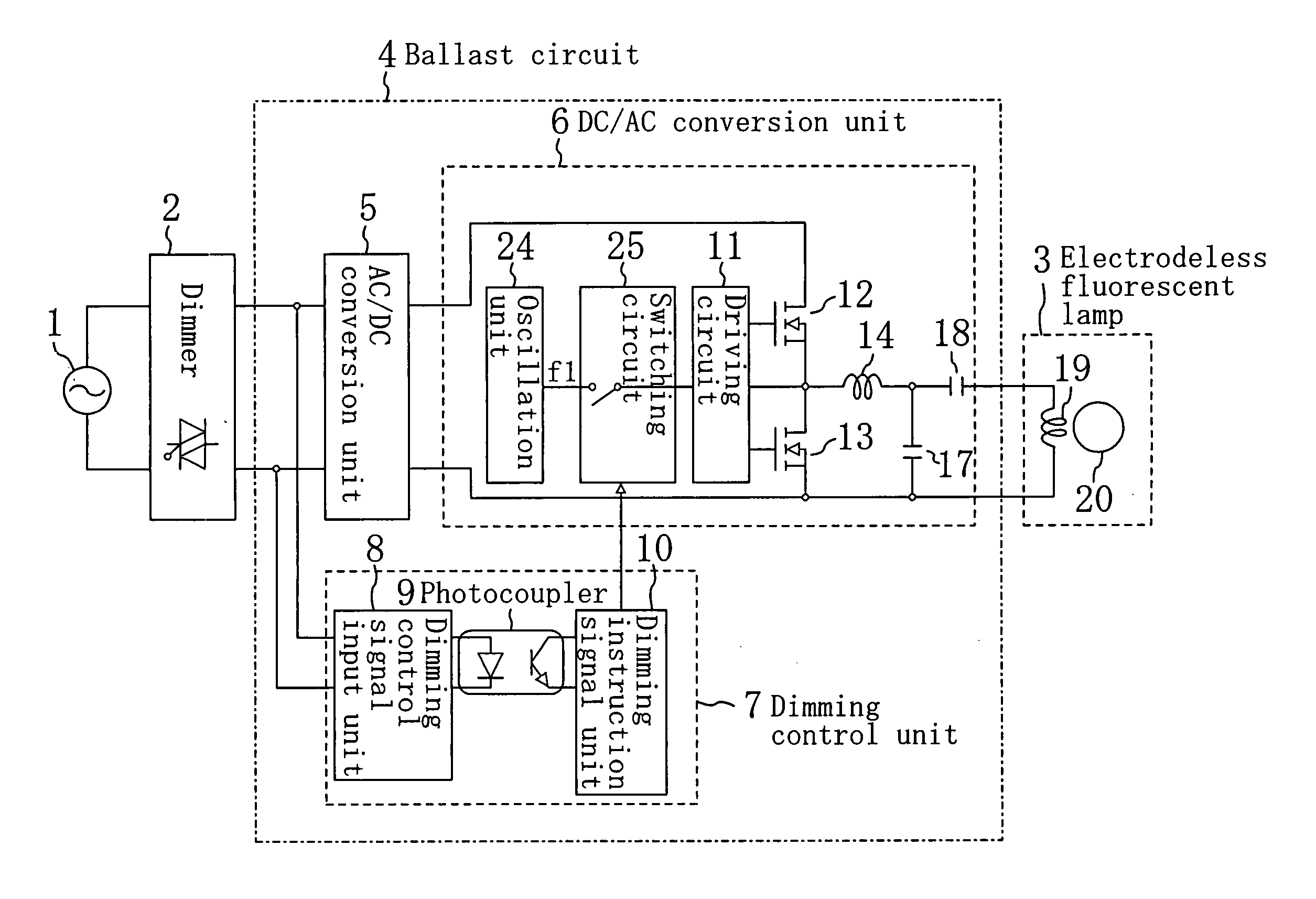
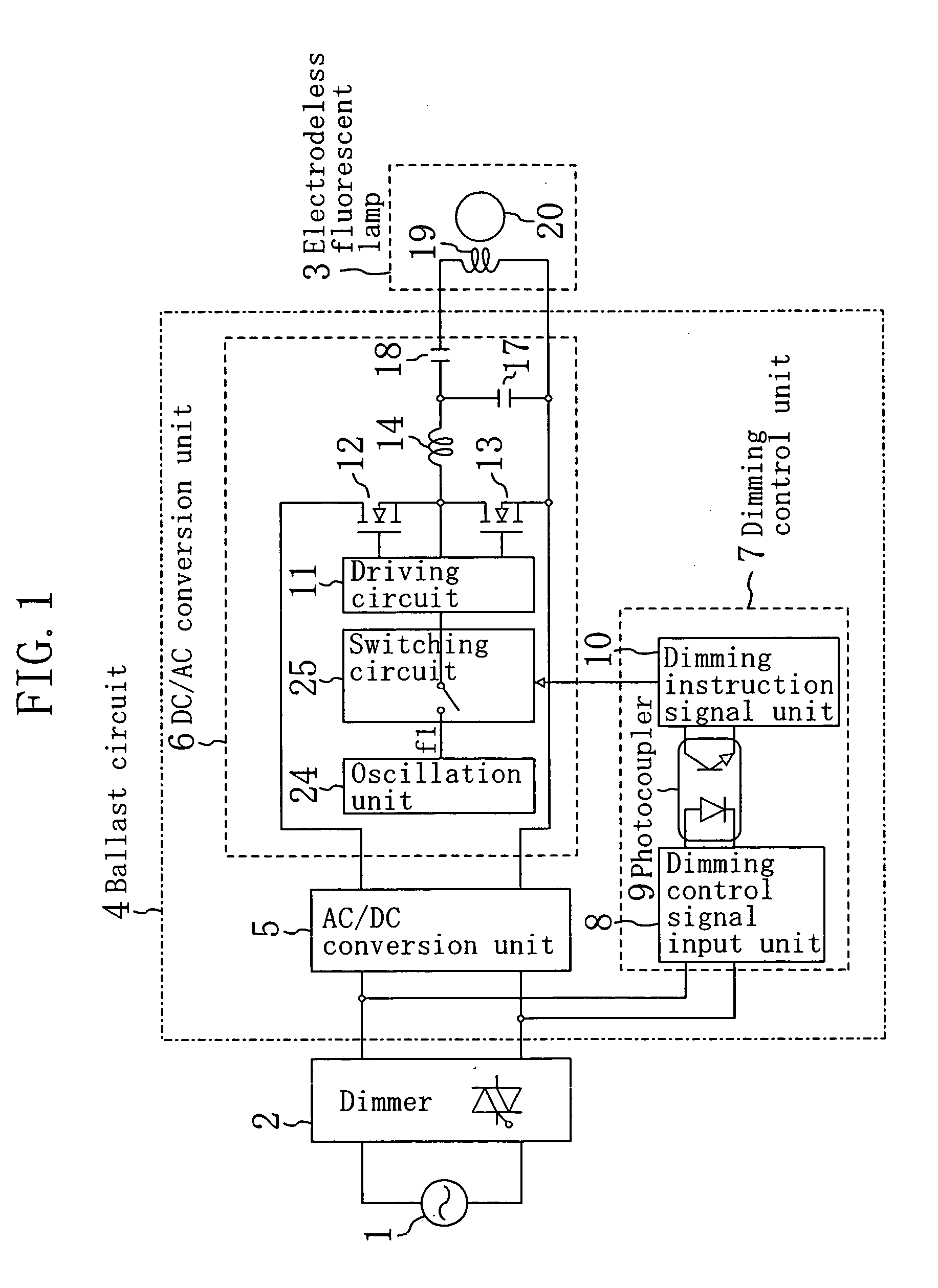
[0043] FIG. 1 schematically illustrates the configuration of a discharge lamp operating apparatus in accordance with EMBODIMENT 1 of the present invention.

[0044] The discharge lamp operating apparatus of EMBODIMENT 1 includes a electrodeless fluorescent lamp 3, a dimmer 2 for phase-controlling the voltage of a commercial power line 1, and a ballast circuit 4 for controlling an operation of the electrodeless fluorescent lamp 3 according to turn-ON and turn-OFF of the voltage phase-controlled by the dimmer 2. The commercial power line 1 is an alternating current power source of, e.g., 60 Hz and 100 V and connected to the dimmer 2. The dimmer 2 is a dimmer using a well-known phase-control technique with a triac. A commercially available incandescent lamp dimmer can be used as the dimmer 2.

[0045] The ballast circuit 4 includes an AC / DC conversion unit 5, a DC / AC conversion unit 6 and a dimming control unit 7. Note that the concepts of the terms of AC / DC conversion unit 5, DC / AC conversi...

embodiment 2

[0062] A discharge lamp operating apparatus in accordance with EMBODIMENT 2 of the present invention has a similar configuration to that of EMBODIMENT 1 but is different from EMBODIMENT 1 in the configuration of the dimming control unit 7.

[0063] This embodiment is different from EMBODIMENT 1 in that a photocoupler 9 whose rise and fall times are longer than those of the photocoupler 9 of EMBODIMENT 1 is used. Thus, in the discharge lamp operating apparatus of this embodiment, the DC / AC conversion unit 6 is intermittently operated so as to be synchronized with turn-ON and turn-OFF of the phase-controlled voltage always with a certain time difference. The certain time difference is a response time of the photocoupler 9 and, for example, is longer than several % of a cycle of an input alternating current voltage.

[0064] Next, characteristics and an operation of a discharge lamp operating apparatus of this embodiment will be described based on FIG. 10.

[0065] In each of FIGS. 10a through ...

embodiment 3

[0071] A discharge lamp operating apparatus in accordance with EMBODIMENT 3 of the present invention is a discharge lamp operating apparatus for performing a dimming operation of an electrodeless fluorescent lamp. The discharge lamp operating apparatus has a similar configuration to that of EMBODIMENT 1 but is different from that of EMBODIMENT 1 in the configuration of the DC / AC conversion unit 6.

[0072] FIG. 3 schematically illustrates a ballast circuit of a discharge lamp operating apparatus in accordance with EMBODIMENT 3 of the present invention. Each of the same components as those of EMBODIMENT 3 is identified by the same reference numeral, and therefore duplicated description will be omitted.

[0073] In FIG. 3, the DC / AC conversion unit 6 includes an oscillation unit 244, a switching circuit 255, a driving circuit 11, MOSFETs 12, 13, a resonance inductor 14 and resonance capacitors 17, 18. Note the oscillation unit 244 includes an oscillation section A of an oscillation frequenc...


PUM


Abstract

A discharge lamp operating apparatus or a compact self-ballasted fluorescent lamp includes: an AC/DC conversion unit 5 for converting an alternating voltage phase-controlled by a dimmer 2 into a direct current voltage; a DC/AC conversion unit 6 for converting an output from the AC/DC conversion unit 5 into a high frequency voltage and applying the high frequency voltage to a discharge lamp, whereby the discharge lamp is intermittently operated; and a dimming control unit 7 which generates a dimming instruction signal for driving the DC/AC conversion unit 6 so that the discharge lamp performs an intermittent operation and outputs the dimming instruction signal to the DC/AC conversion unit via a photocoupler 9, and synchronizes the timings of turn-ON and turn OFF of the phase-controlled voltage with the timings of turn-ON and turn OFF of an operation of the DC/AC conversion unit 6, respectively.

Description

[0001] The present invention is related to electrodeless discharge lamp operating apparatuses, electrodeless compact self-ballasted fluorescent lamps and discharge lamp operating apparatuses, and more particularly relates to an operating apparatus for controlling light with an incandescent lamp dimmer.[0002] Fluorescent lamps have higher efficiency and a longer lifetime than incandescent lamps. Therefore, fluorescent lamps are now widely used in view of global environmental protection and also for economical reason. Moreover, in recent years, compact self-ballasted fluorescent lamps in which a fluorescent lamp and a ballast circuit are assembled as one unit have attracted attention as an energy conservation type light source for use in houses, hotels, restaurants and the like. Besides, a compact self-ballasted fluorescent lamp as it is can be used easily in place of an incandescent lamp. Therefore, use of compact self-ballasted fluorescent lamps is apparently going to spread more an...

Claims


Application Information

Patent Timeline
Patent Type & Authority Applications(United States)
IPC IPC(8): H05B41/28H05B41/282H05B41/392
CPCH05B41/2806H05B41/2828H05B41/3924Y10S315/04H05B41/3927Y02B20/185Y02B20/22H05B41/3925Y02B20/00
Inventor TAKAHASHI, KENICHIROKOMINAMI, SATOSHIMIYAZAKI, KOJIKURACHI, TOSHIAKIMATSUBAYASHI, YOKO
Owner PANASONIC CORP
Why Eureka
Try Eureka