Mixed mode control for dimmable fluorescent lamp

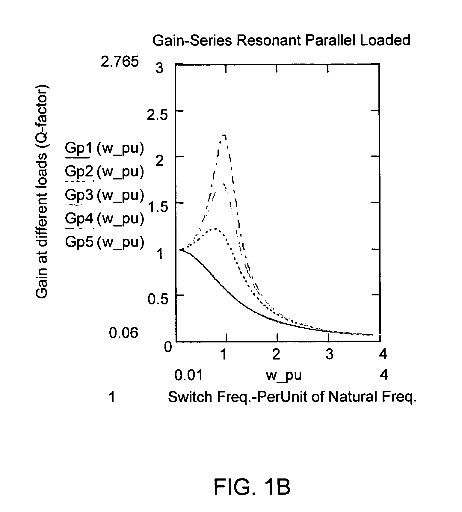
a fluorescent lamp and mixing mode technology, applied in the direction of lighting devices, instruments, light sources, etc., can solve the problems of ineffective adjustment of light output of fluorescent lamps b>12/b>, inability to meet the high gain required at high impedance for ignition and low load dimming, and flat curves, etc., to achieve the effect of reducing the pulse width of both switches and reducing the turn on time of one of the switching elements

Active Publication Date: 2008-09-02
MARVELL ASIA PTE LTD
View PDF8 Cites 52 Cited by
  • Summary
  • Abstract
  • Description
  • Claims
  • Application Information

AI Technical Summary

Benefits of technology

[0021]In the conventional duty cycle control, the dimming is achieved by reducing pulse width of both switches. However, in the present invention

Problems solved by technology

The series LC resonant series loaded and series parallel resonance circuits are not commonly used for electronic ballast because they behave like a band-pass filter, and so cannot satisfy the high gain required at high impedance for ignition and low load dimming.
However, in some threshold of low dim range, the curve becomes flat, and the light output of the fluorescent lamp 12 cannot be effectively adjusted by changing the frequency fsw.
Another disadvantage of convention

Method used


Image

  • Mixed mode control for dimmable fluorescent lamp
  • Mixed mode control for dimmable fluorescent lamp
  • Mixed mode control for dimmable fluorescent lamp

Examples


Embodiment Construction

[0036]Objects and advantages of the present invention will become apparent from the following detailed description.

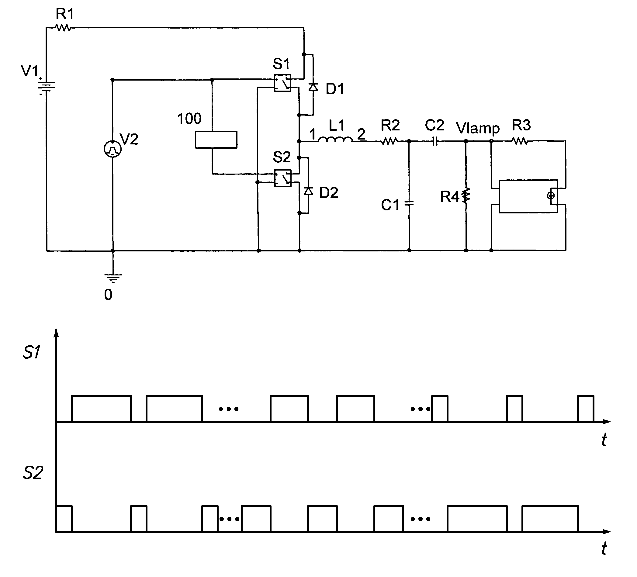
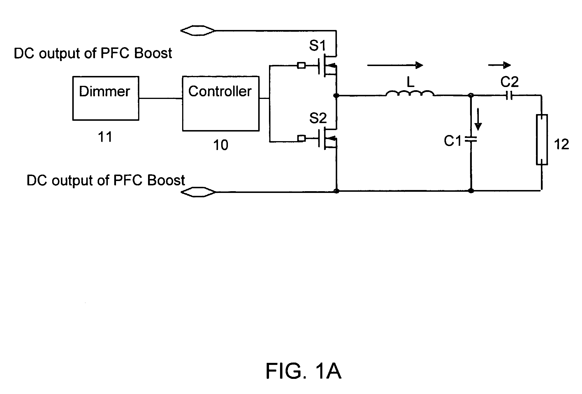
[0037]The present invention employs the general structure of the conventional series resonant parallel loaded ballast with double switch choppers. FIG. 4 shows a mixed mode ballast for controlling a dimmable fluorescent lamp according to one embodiment of the present invention. To provide a smooth and continuous control range of 100% to 10% or lower light control, the present invention provides a mixed mode controller 100 to control the switching elements S1 and S2. The present invention also optimizes the values of L, C1 and C2 of the ballast. The switching elements could be transistors, specifically, FETs.

[0038]In one embodiment, when the load is adjusted from 100% to near threshold of losing the sensitivity to frequency control, the method of the present invention uses the conventional frequency control, and makes use of its symmetrical waveforms, i.e., D=0.5. FIG. 5...


PUM


Abstract

A mixed mode control for dimmable fluorescent lamp provides a smooth and continuous control of output of the lamp. A load threshold, below which the output of the discharge lamp could not be effectively controlled by the conventional frequency control, is determined. During the dimming of the discharge lamp, when the load is not lower than the load threshold, the conventional frequency control is employed. However, when the load is lower than the load threshold, a complementary duty cycle control is used.

Description

CROSS-REFERENCE TO RELATED APPLICATIONS[0001]This application claims the benefit of Provisional Application No. 60 / 540,222, filed Jan. 29, 2004. This application incorporates the provisional application by reference.BACKGROUND OF THE INVENTION[0002]1. Field of the Invention[0003]The present invention relates to control of a dimmable discharge lamp, and more specifically to generation of a dimming current for a fluorescent lamp.[0004]2. Description of the Related Art[0005]The electronic ballast for fluorescent lamp dimming control could use either a series LC resonant series loaded circuit, a series resonance parallel loaded circuit, or a series parallel resonance circuit, controlled by either the frequency or the duty cycle of input voltage pulses. The existing duty cycle control employs symmetrically chopped pulses. The series LC resonant series loaded and series parallel resonance circuits are not commonly used for electronic ballast because they behave like a band-pass filter, an...

Claims


Application Information

Patent Timeline
IPC IPC(8): H05B37/02
CPCH05B41/3927H05B41/3925
Inventor HAMDAD, FATEMEHNOTOHAMIPRODJO, HUBERTUS
Owner MARVELL ASIA PTE LTD
Why Eureka
Try Eureka