
Low frequency triggered electronic ballast

a low-frequency trigger and electronic ballast technology, applied in sustainable buildings, energy-saving lighting, machines/engines, etc., can solve the problems of increasing manufacturing costs and deteriorating efficiency of the ballast system, and achieve the effects of reducing manufacturing costs, improving system stability, and reducing voltage rating power devices

Inactive Publication Date: 2007-01-11
DJ AUTO COMPONENTS CORP
View PDF7 Cites 3 Cited by
  • Summary
  • Abstract
  • Description
  • Claims
  • Application Information

AI Technical Summary

Benefits of technology

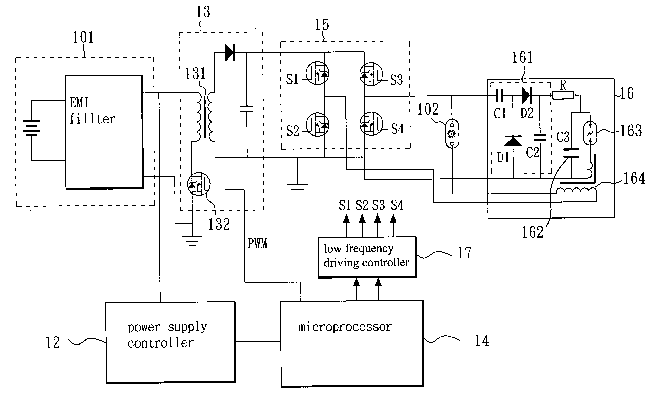
[0008] The present invention can use a low frequency square pulse output by the full-bridge circuit to produce a high DC voltage by the voltage doubling rectifying circuit to charge the energy storage capacitor, which results in the use of the lower voltage rating power devices for the HID lamp ballast system compared with conventional system and reduces the manufacturing costs.
[0009] The electronic ballast of the present invention further comprises a low frequency driving controller electrically connected between the microprocessor and the full-bridge circuit, the low frequency driving controller controlling the full-bridge circuit to output a low frequency square voltage pulse at a specific frequency. Therefore, the low frequency driving controller may control the full-bridge circuit to output a medium-level voltage square pulse with a stable low frequency for increasing the stability of the system.
[0010] Furthermore, the microprocessor detects at least one value of a group of: the voltage value of the power supply, the current value of the low voltage switching element, the voltage value of the HID lamp, or the current value of the HID lamp; wherein when at least one value being detected is increased, the microprocessor correspondingly decreases the pulse-width of the PWM signal. Therefore, the microprocessor may change the pulse-width to avoid damaging the low voltage switching element or other related devices according to the detected voltage value or current value of the HID lamp.

Problems solved by technology

That makes the ballast system to deteriorate the efficiency and to increase the manufacturing cost.

Method used


Image

  • Low frequency triggered electronic ballast
  • Low frequency triggered electronic ballast
  • Low frequency triggered electronic ballast

Examples


Embodiment Construction

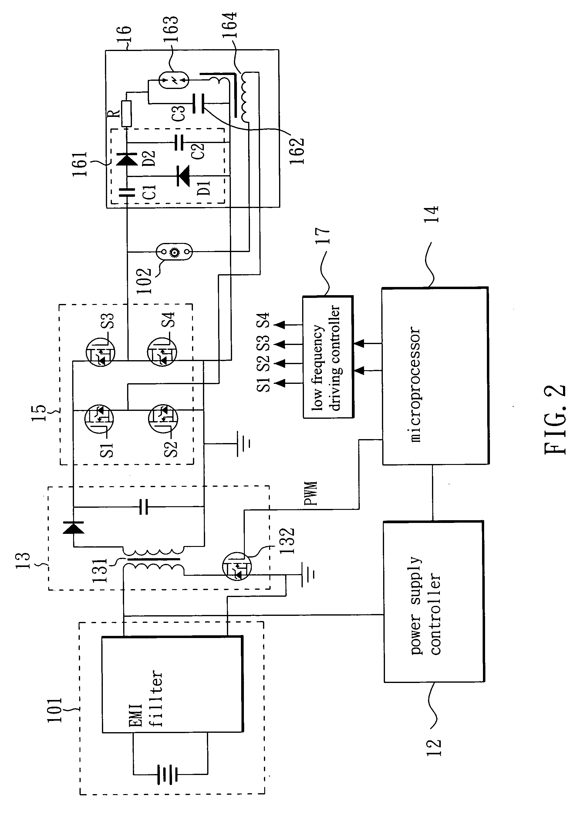
[0016] Please refer to FIG. 2 and FIG. 3. FIG. 2 is a functional block drawing of an embodiment according to the present invention. FIG. 3 shows an embodiment according to the setting for the operation of the present invention. In this embodiment, electronic ballast 10 is electrically connected to an HID lamp 102 of a vehicle 1 and a power supply 101. In this embodiment, the electronic ballast 10 is a part of a vehicle headlight assembly, and comprises: a power supply controller 12, a DC-DC circuit 13, a microprocessor 14, a full-bridge driving circuit 15, and an ignition circuit 16. In this embodiment, the power supply controller 12 is preferably an on-off switch or some other equivalent device, such as a button. The power supply controller 12 is electrically connected to the power supply 101 and is used to control the power supply to supply electric power to the electronic ballast. In this invention, the power supply 101 is a 12 voltage power supply and comprises an electromagneti...


PUM


Abstract

An electronic ballast, The ballast use voltage controlling the energy storage capacitor, Furthermore, the electronic ballast continuously detects the current value and the voltage value of the HID lamp, change the pulse-width signal according to the detection result to control the HID lamp within a stable working current.

Description

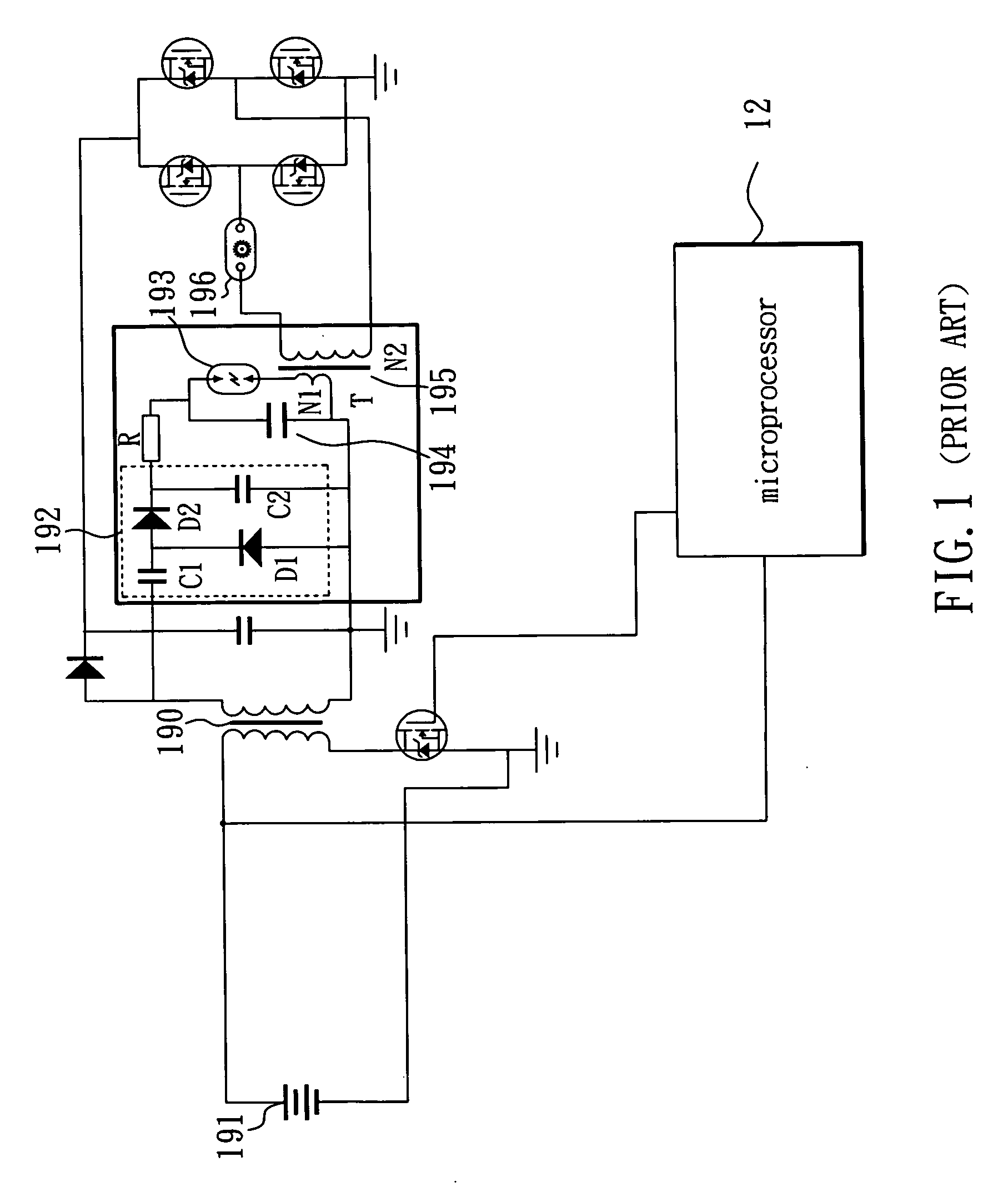
BACKGROUND OF THE INVENTION [0001] 1. Field of the Invention [0002] The present invention relates to electronic ballast, and more particularly, to low frequency triggered electronic ballast. [0003] 2. Description of the Related Art [0004] Generally, under normal conditions, the two electrodes of a high intensity discharge (HID) lamp do not conduct with each other; in order to turn on the HID lamp, a high voltage pulse must first be applied, which is in the range of 20˜25K volts for stable ignition. Electronic ballast is used to provide not just an ignition pulse, but also a low frequency AC voltage about 80-120 volts to sustain a stable arc inside the lamp. The electronic ballast also controls the current to protect the lamp and other components. [0005] In the conventional system as shown in FIG. 1, a high frequency DC-DC converter in the front of ballast using a pulse-width modulation (PWM) signal to control a transformer 190 boosts the 12V car battery 191 up to the 80-300V DC volt...

Claims


Application Information

Patent Timeline
Patent Type & Authority Applications(United States)
IPC IPC(8): F02P3/08H05B41/20H05B41/288
CPCY02B20/202H05B41/2886Y02B20/00
Inventor CHU, SING
Owner DJ AUTO COMPONENTS CORP
Learn More