Pulsed combustion engine

a combustion engine and pulse technology, applied in the direction of combustion type, turbine/propulsion engine ignition, vessel construction, etc., can solve the problem of notoriously inefficient combustion of conventional gas turbine engines

Active Publication Date: 2007-10-09
RTX CORP
View PDF18 Cites 23 Cited by
  • Summary
  • Abstract
  • Description
  • Claims
  • Application Information

AI Technical Summary

Benefits of technology

[0005]In various implementations, the inner wall may have an array of volumes (pockets). The apertures may include, for each of the pockets: a first aperture between the interior of such pocket and a space between the inner and outer walls; and a second aperture between the interior of the pocket and the interior space. An intermediate wall may be located between the outer wall and the inner wall and may have a number of apertures. The cooling air may be directed through the intermediate wall before reaching the inner wall. The inner wall may include an inner layer and an outer layer secured to the inner layer. The outer layer may have an array of three-dimensional excursion features (e.g., dome-like blisters) cooperating with the inner layer to form the pockets. The ignition system may be effective to induce detonation of the charges.

Problems solved by technology

Such conventional gas turbine engine combustion is notoriously inefficient and has led to many efforts to improve efficiency.

Method used


Image

  • Pulsed combustion engine
  • Pulsed combustion engine
  • Pulsed combustion engine

Examples


Embodiment Construction

[0022]A new combustor tube configuration may be applied to a turbine engine. Exemplary turbine engines and combustors may be variations on those shown in U.S. Patent Publication Nos. 20040123582A1 and 20040123583A1 and European Patent Convention publications EP1435447A1 and EP1435440A1 (the disclosures of which are incorporated by reference herein as if set forth at length).

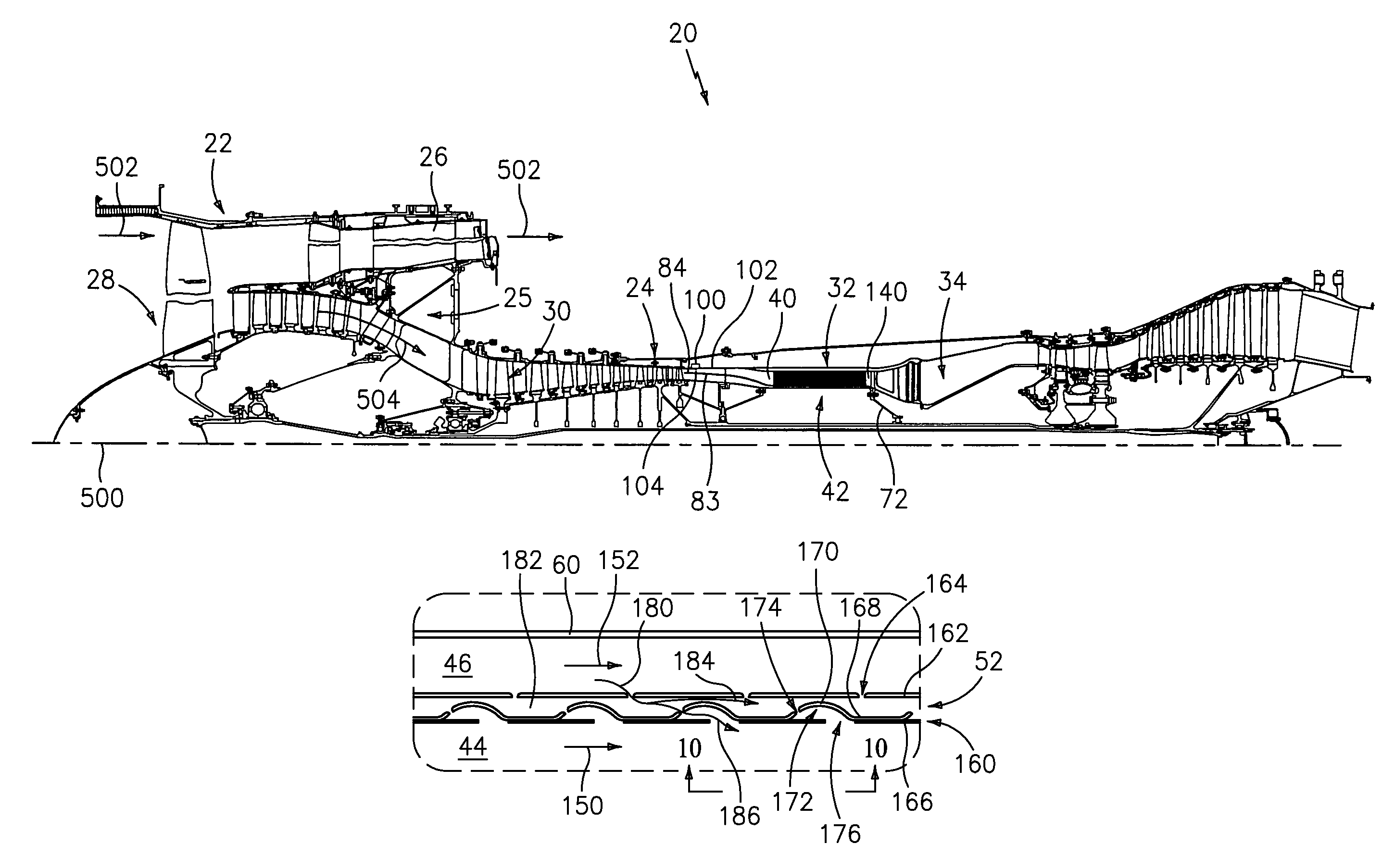
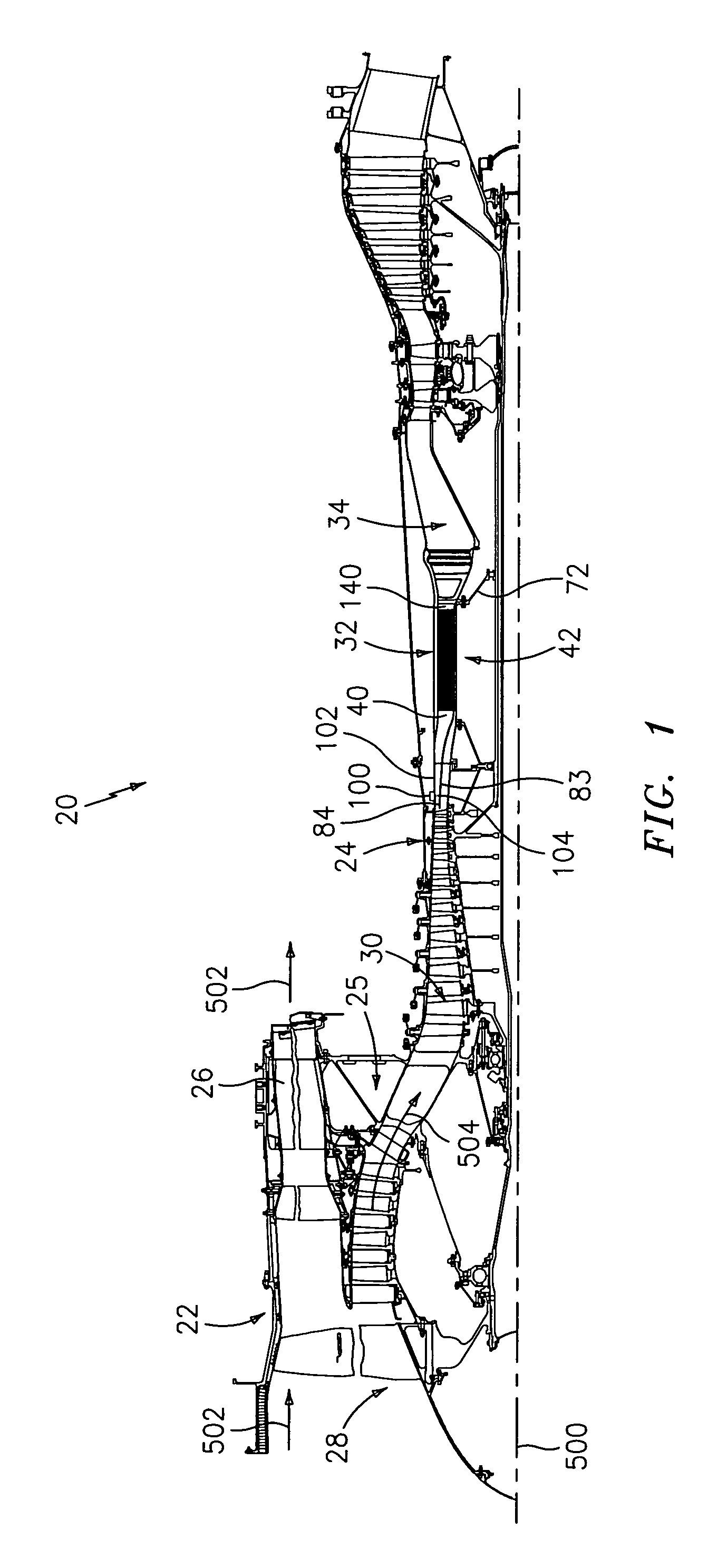
[0023]FIG. 1 shows a turbofan engine 20 having central longitudinal axis 500, a duct 22 and a core 24. The duct is supported relative to a case assembly 25 of the core by vanes 26. Of inlet air entering the duct, a fan 28 drives a bypass portion along a first flow path 502 radially between the duct and the core and core portion along a second flowpath 504 through the core. In the core downstream of the fan, a compressor section 30 having alternating rings of rotor blades and stator vanes compresses the core air and delivers it further downstream to a combustor section 32 where it is mixed with fuel and combusted....


PUM


Abstract

A pulsed combustion apparatus includes a conduit having an outer wall and an inner wall. The inner wall has a number of apertures. An interior space is separated from the outer wall by the inner wall. An induction system is positioned to cyclicly admit charges to the interior space. An ignition system is positioned to ignite the charges. Flow directing surfaces are positioned to at least cyclicly direct cooling air through the apertures.

Description

BACKGROUND OF THE INVENTION[0001]This invention relates to pulse combustion, and more particularly to hybrid pulse combustion turbine engines.[0002]In a conventional gas turbine engine, combustion occurs in a continuous, near constant pressure (Rankine cycle), mode. Such conventional gas turbine engine combustion is notoriously inefficient and has led to many efforts to improve efficiency.[0003]It has been proposed to apply the more efficient combustion of near constant volume combustion pulse detonation engines (PDEs) to turbine engine combustors. In a generalized PDE, fuel and oxidizer (e.g., oxygen-containing gas such as air) are admitted to an elongate combustion chamber at an upstream inlet end, typically through an inlet valve as a mixture (e.g., of hydrocarbon fuel droplets or vapor in air). Upon introduction of this charge, the valve is closed and an igniter is utilized to detonate the charge (either directly or through a deflagration to detonation transition). A detonation ...

Claims


Application Information

Patent Timeline
Patent Type & Authority Patents(United States)
IPC IPC(8): F02C5/00
CPCF23C15/00F23R3/002F23R3/08F23R7/00F23R3/56
Inventor NORRIS, JAMES W.NORDEEN, CRAIG A.TWELVES, JR., WENDELL V.
Owner RTX CORP
Why Eureka
Try Eureka