Inkjet head

a technology of inkjet head and inkjet printing, which is applied in the field of inkjet head, can solve the problems of weak flexible sealing film breaking, difficult for the deformation of the diaphragm to satisfactorily absorb a large fluctuation, etc., and achieve the effect of facilitating the absorbing of fluctuation

Active Publication Date: 2007-10-09
BROTHER KOGYO KK
View PDF27 Cites 7 Cited by
  • Summary
  • Abstract
  • Description
  • Claims
  • Application Information

AI Technical Summary

Benefits of technology

[0009]It is an object of the invention to provide an inkjet head in which a fluctuation of pressure occurring in an wink channel at the time of ink supply can be absorbed surely, and a flexible film that absorbs the fluctuation of pressure is hardly broken.
[0012]The volume (area) of the ink reservoir is set to be wider than any other portion of the ink supply channel because the ink reservoir can once reserve ink. In addition, the flexible film for absorbing the ink pressure is provided in the ink reservoir. Accordingly, the effect of absorbing the fluctuation of pressure due to the flexible film is enhanced. Thus, the fluctuation of ink pressure occurring due to ink supply into the ink reservoir or the like can be attenuated quickly. In addition, since the flexible film is provided in the ink reservoir and is not exposed to the outside, the flexible film is hardly broken even when external impact or the like acts on the reservoir unit for some reason.
[0016]According to another aspect of the invention, the other of the two plates has a plurality of second space formation holes on the surfaces, and the second ink pass hole is formed in the region between the two second space formation holes. Since the second ink pass hole is formed between the two second space formation holes thus, the second space formation holes and the second ink pass hole can be disposed efficiently within one plane. Thus, the reservoir unit can be miniaturized.
[0018]Since the two space formation holes are made to communicate with each other through the recess portion, of the flexible film, portions opposed to the two second space formation holes can be vibrated integrally. Thus, the fluctuation of pressure can be absorbed more efficiently.
[0019]According to another aspect of the invention, the ink reservoir further includes an atmosphere communication hole that makes communication between the second space formation hole and an outside of the reservoir unit. Accordingly, the flexible film is hardly affected by the internal pressure of the air in the second space. Thus, the fluctuation of pressure can be absorbed more efficiently.

Problems solved by technology

However, when the sealing film is exposed to the outside as in the inkjet head disclosed in JP-A-2003-145761, there is a fear that the flexible sealing film which is weak in strength is broken by impact or the like acting thereon externally.
Accordingly, the area with which the diaphragm contacts with ink is so small that it is difficult for the deformation of the diaphragm to satisfactorily absorb a large fluctuation of pressure occurring at the time of ink supply.

Method used


Image

  • Inkjet head
  • Inkjet head
  • Inkjet head

Examples


Embodiment Construction

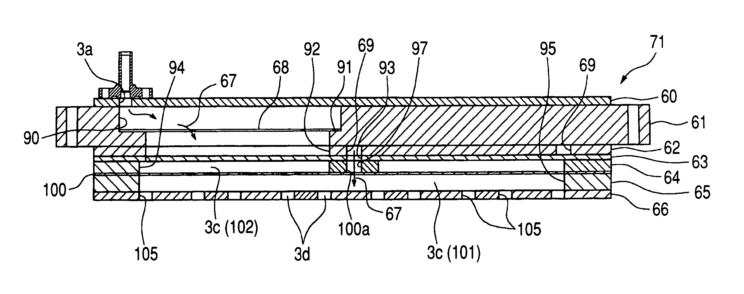
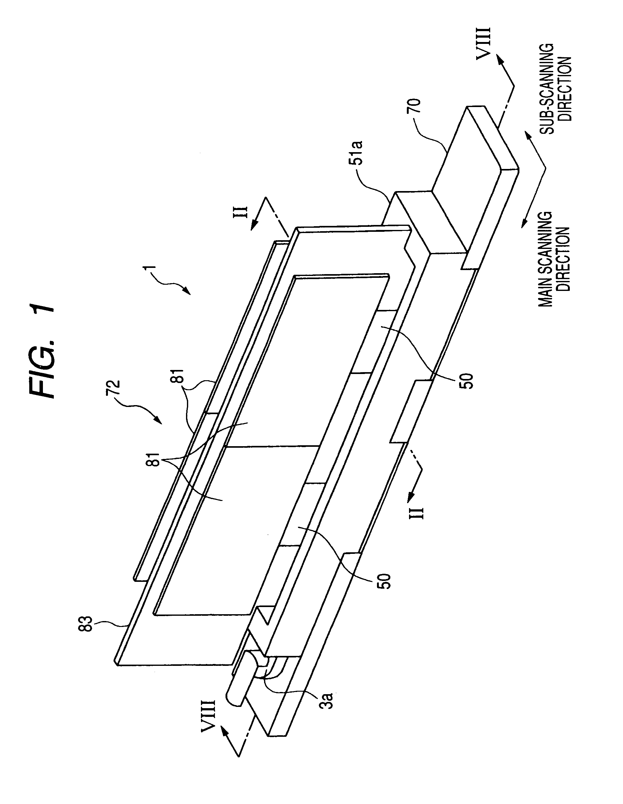
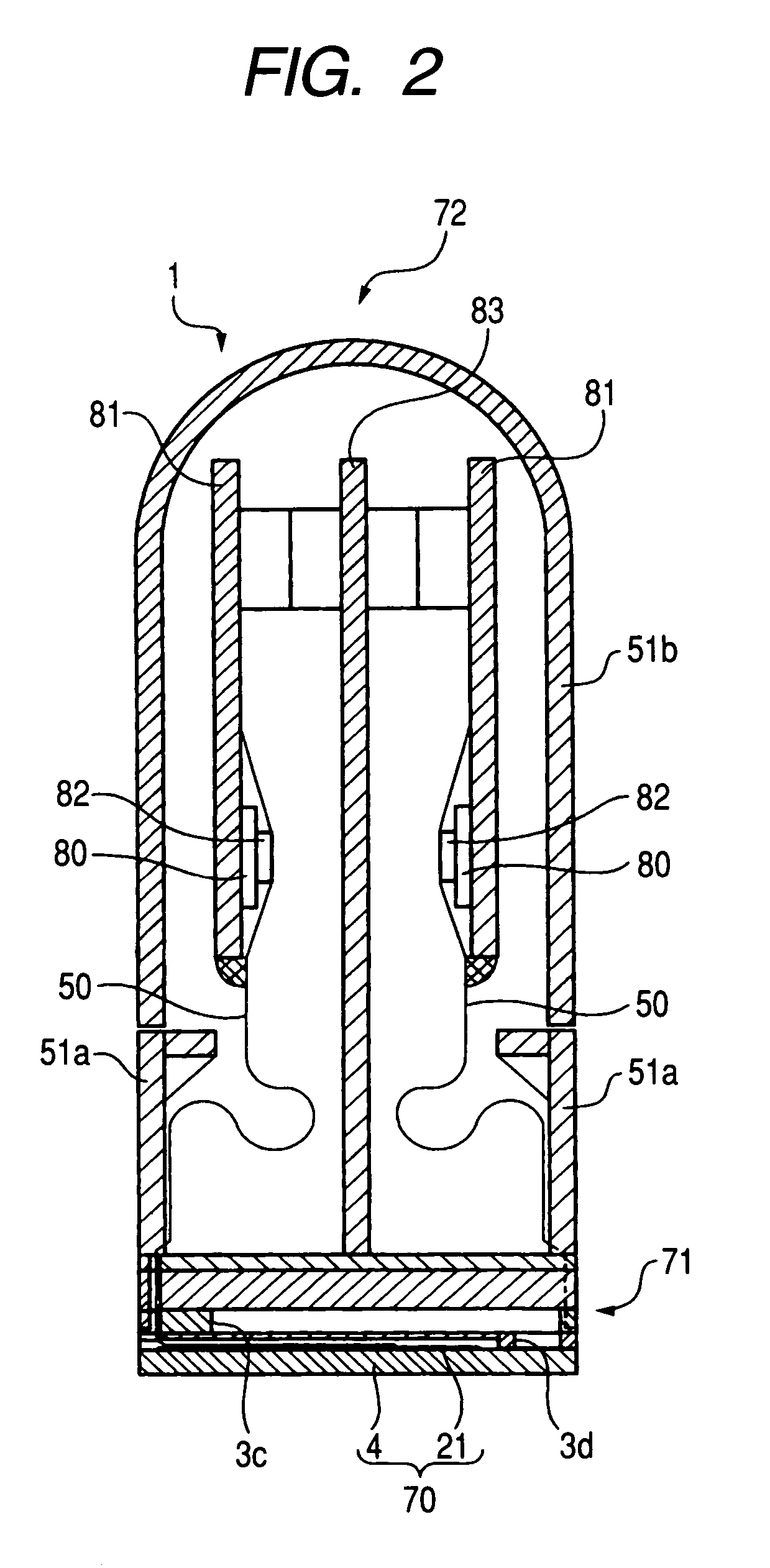
[0037]An embodiment of the invention will be described with reference to the drawings. As shown in FIGS. 1 and 2, an inkjet head 1 has a head body 70, a reservoir unit 71, a head control portion 72, a lower cover 51a and an upper cover 51b. The head body 70 extends in a main scanning direction for ejecting ink onto paper. The head body 70 has a rectangular planar shape. The reservoir unit 71 is disposed on the top of the head body 70. In the reservoir unit 71, an ink reservoir 3c for reserving ink to be supplied to the head body 70 is formed. The head control portion 72 is disposed above the reservoir unit 71 and for controlling the head body 70. The lower cover 51a and the upper cover 51b are provided for protecting the inside of the inkjet head 1 from ink droplets. Incidentally, in FIG. 1, as a matter of convenience in explanation, the upper cover 51b is not shown.

[0038]The head body 70 includes a channel unit 4 in which ink channels are formed, and a plurality of actuator units 2...


PUM


Abstract

A reservoir unit of an inkjet head has a plurality of laminated reservoir plates that forms an ink supply channel, and a flexible film that absorbs a fluctuation of pressure of ink in an ink reservoir. The flexible film is provided between adjacent two reservoir plates of the laminated plates. The adjacent two reservoir plates forms the ink reservoir. The flexible film partitions the ink reservoir into a first space to be filled with ink and a second space to be filled with no ink.

Description

BACKGROUND OF THE INVENTION[0001]1. Filed of the Invention[0002]The present invention relates to an inkjet head of in inkjet recording apparatus, which ejects ink onto a recording medium to perform printing thereon.[0003]2. Description of the Related Art[0004]In inkjet heads, ink supplied from an ink tank is distributed from a common ink chamber to a plurality of pressure chambers, and a pulsed pressure wave is applied selectively to each pressure chamber so as to eject ink from a nozzle communicating with the pressure chamber. Of such inkjet heads, some have an ink reservoir for reserving ink supplied from the ink tank and supplying the reserved ink to the plurality of pressure chambers in order to supply ink to the pressure chambers stably.[0005]In an ink channel from the ink tank to each nozzle through the ink reservoir, each pressure chamber, etc., there occurs a fluctuation of ink pressure due to a water hammer phenomenon etc. caused by ink inertia when the ink is supplied from...

Claims


Application Information

Patent Timeline
Patent Type & Authority Patents(United States)
IPC IPC(8): B41J2/175B41J2/045B41J2/055B41J2/14
CPCB41J2/14209B41J2002/14217B41J2002/14225B41J2202/20B41J2002/14419B41J2002/14459B41J2002/14491B41J2002/14306B41J2202/08
Inventor HIROTA, ATSUSHIWATANABE, HIDETOSHICHIKAMOTO, TADANOBU
Owner BROTHER KOGYO KK
Why Eureka
Try Eureka