Two edge deburring tool

a technology of deburring tool and workpiece, which is applied in the direction of shaping cutter, manufacturing tools, wood veneer joining, etc., can solve the problems of reducing the efficiency of automated machine tool operation, and affecting the efficiency of automatic machine tool operation

Inactive Publication Date: 2007-10-09
CLAYTON STEPHEN D
View PDF40 Cites 31 Cited by
  • Summary
  • Abstract
  • Description
  • Claims
  • Application Information

AI Technical Summary

Problems solved by technology

These burrs have many associated issues including: they detract from the aesthetic look of the finished product; they form a sharp edge that can cause cuts and scrapes; and, when they eventually break off, they can cause electrical shorts or they can cause other failures to mechanisms such as gears and bearings.
The added operator intervention greatly reduces the efficiency of the automated machine tool operation.
This tool has opposing cutting edges but is not designed to operate at high speeds, as required when the workpiece material is steel.
Furthermore, the described tool is adjustable, making it difficult to obtain an accurate setting of the cutting surfaces in relationship to the width of the workpiece.

Method used


Image

  • Two edge deburring tool
  • Two edge deburring tool
  • Two edge deburring tool

Examples


Embodiment Construction

[0015]Reference will now be made in detail to the presently preferred embodiments of the invention, examples of which are illustrated in the accompanying drawings. Throughout the following detailed description, the same reference numerals refer to the same elements in all figures.

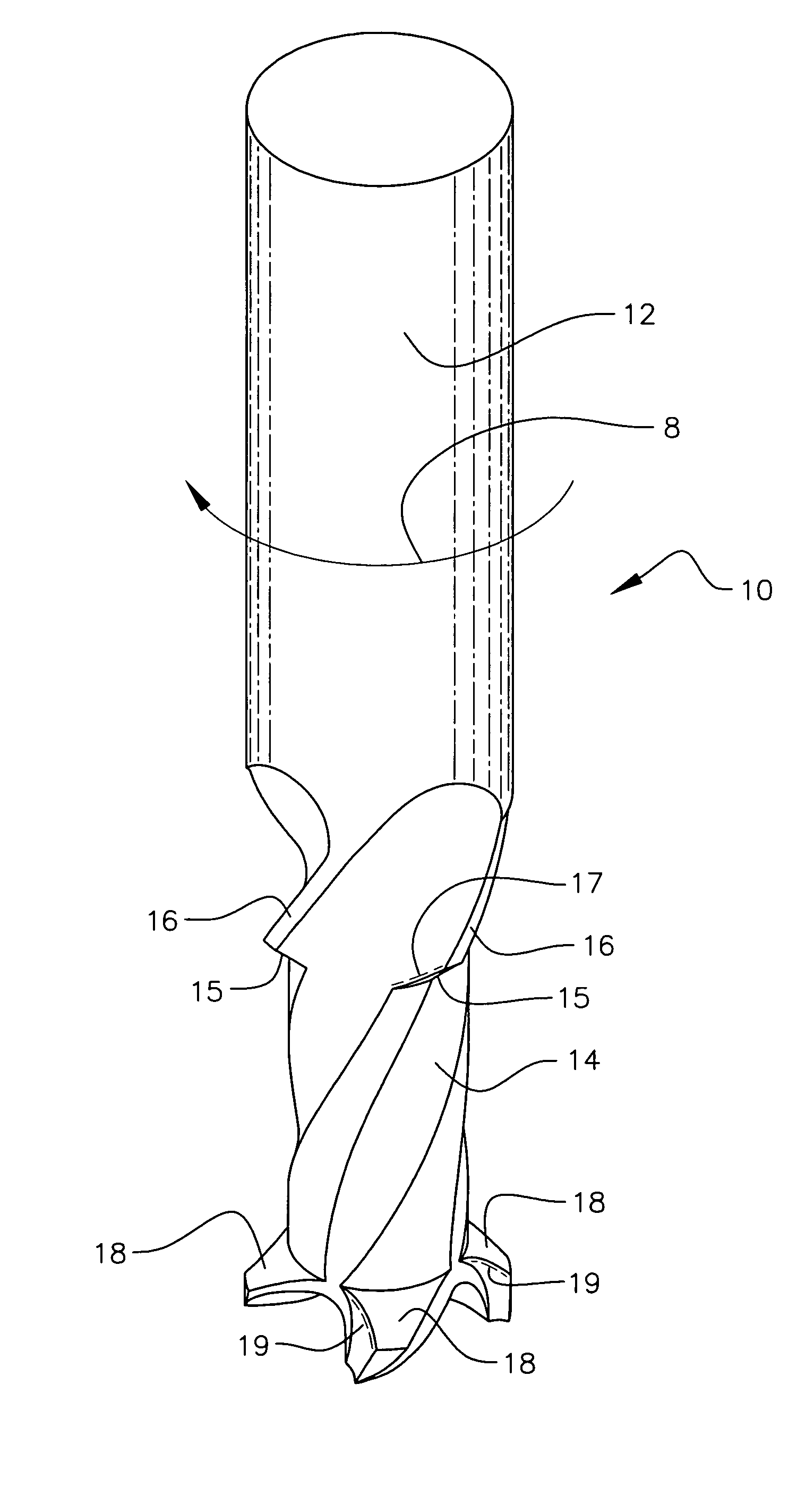
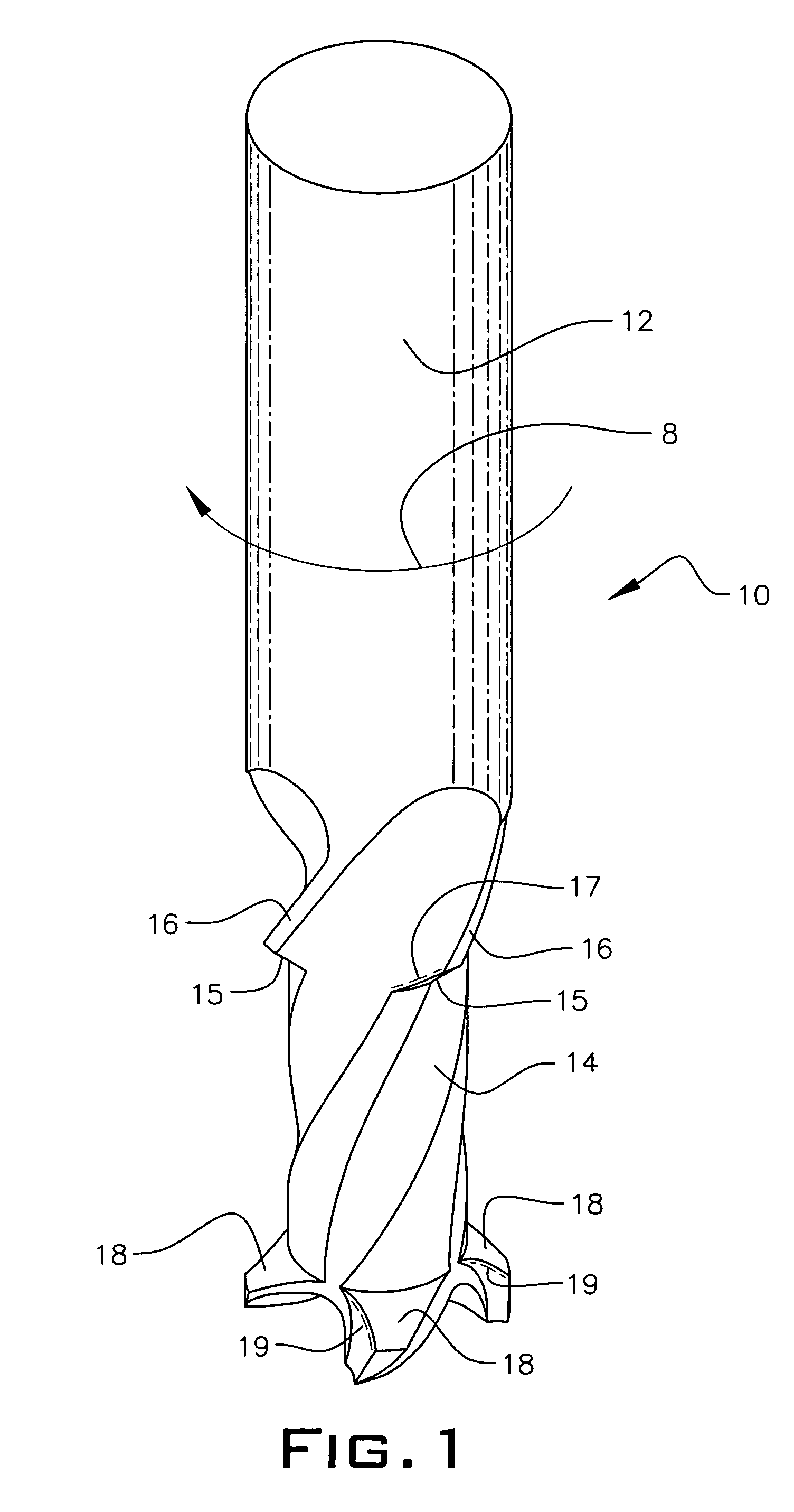
[0016]Referring to FIG. 1, a deburr tool of a first embodiment of the present invention is shown. The deburr tool 10 is fabricated from a mill end or drill bit, either having straight flutes or spiral flutes. The shaft 12 of the deburr tool 10 is intended for insertion into a source of rotation such as a high-speed milling machine or computer aided manufacturing system. In one embodiment, the deburr tool 10 is configured to rotate in one direction 8, but in an alternate embodiment, a deburr tool 10 is configured to rotate in the opposite direction. It is preferred that the deburr tool 10 be made from hardened steel or carbide steel to withstand repeated high-speed operations.

[0017]The deburr tool 10 is cons...


PUM

PropertyMeasurementUnit
angleaaaaaaaaaa
rotationaaaaaaaaaa
angleaaaaaaaaaa

Abstract

A rotating tool for simultaneously deburring two surfaces of a workpiece is disclosed including a rotatable shaft having a first end and a second end with a first deburr surface on the first end facing towards the second end and having a first angle. A second deburr surface is formed between the first end and the second end facing towards the first end and having a second angle. The distance between a first mid-point of the first deburr surface and a second mid-point of the second deburr surface is substantially equal to a width of the workpiece.

Description

BACKGROUND OF THE INVENTION[0001]1. Field of the Invention[0002]This invention relates to the field of deburring and more particularly to a device for deburring two edges of a workpiece.[0003]2. Description of the Related Art[0004]Deburring tools are well known in the industry. When a metal object or workpiece is cut or bored, metal fragments called burrs occur on its edges. These burrs have many associated issues including: they detract from the aesthetic look of the finished product; they form a sharp edge that can cause cuts and scrapes; and, when they eventually break off, they can cause electrical shorts or they can cause other failures to mechanisms such as gears and bearings. Burrs are removed in several ways including from passing a drill bit along one of the edges or filing. In addition, a deburring tool sometimes chamfers the edges of the workpiece.[0005]Presently, in an automated machine tool process, a drill bit or end mill is used to deburr one edge of a workpiece after...

Claims


Application Information

Patent Timeline
Patent Type & Authority Patents(United States)
IPC IPC(8): B23C3/00B23C1/00B23C5/16
CPCB23C3/12B23C5/10B23C2220/16B23C2265/08Y10T407/1946Y10T409/304256Y10T409/304144Y10T409/303808B23C2270/14
Inventor CLAYTON, STEPHEN D.
Owner CLAYTON STEPHEN D
Why Eureka
Try Eureka