Gauge having a magnetically driven pointer rotation device

a technology of magnetic drive and rotation device, which is applied in the direction of fluid pressure measurement using inductance variation, identification means, instruments, etc., can solve the problems of reducing operating efficiency and prone to leakage of seals

Inactive Publication Date: 2007-10-16
DWYER INSTR
View PDF21 Cites 14 Cited by
  • Summary
  • Abstract
  • Description
  • Claims
  • Application Information

AI Technical Summary

Problems solved by technology

Mechanical or adhesive seals between the pointer assembly and the separating wall can be used, but the seals are prone to leakage and allow fluid to enter the indicator chamber.
It is undesirable to have fluid come into contact with the pointer assembly as the fluid causes contamination of the pointer assembly and decreased operating efficiency.

Method used


Image

  • Gauge having a magnetically driven pointer rotation device
  • Gauge having a magnetically driven pointer rotation device
  • Gauge having a magnetically driven pointer rotation device

Examples


Embodiment Construction

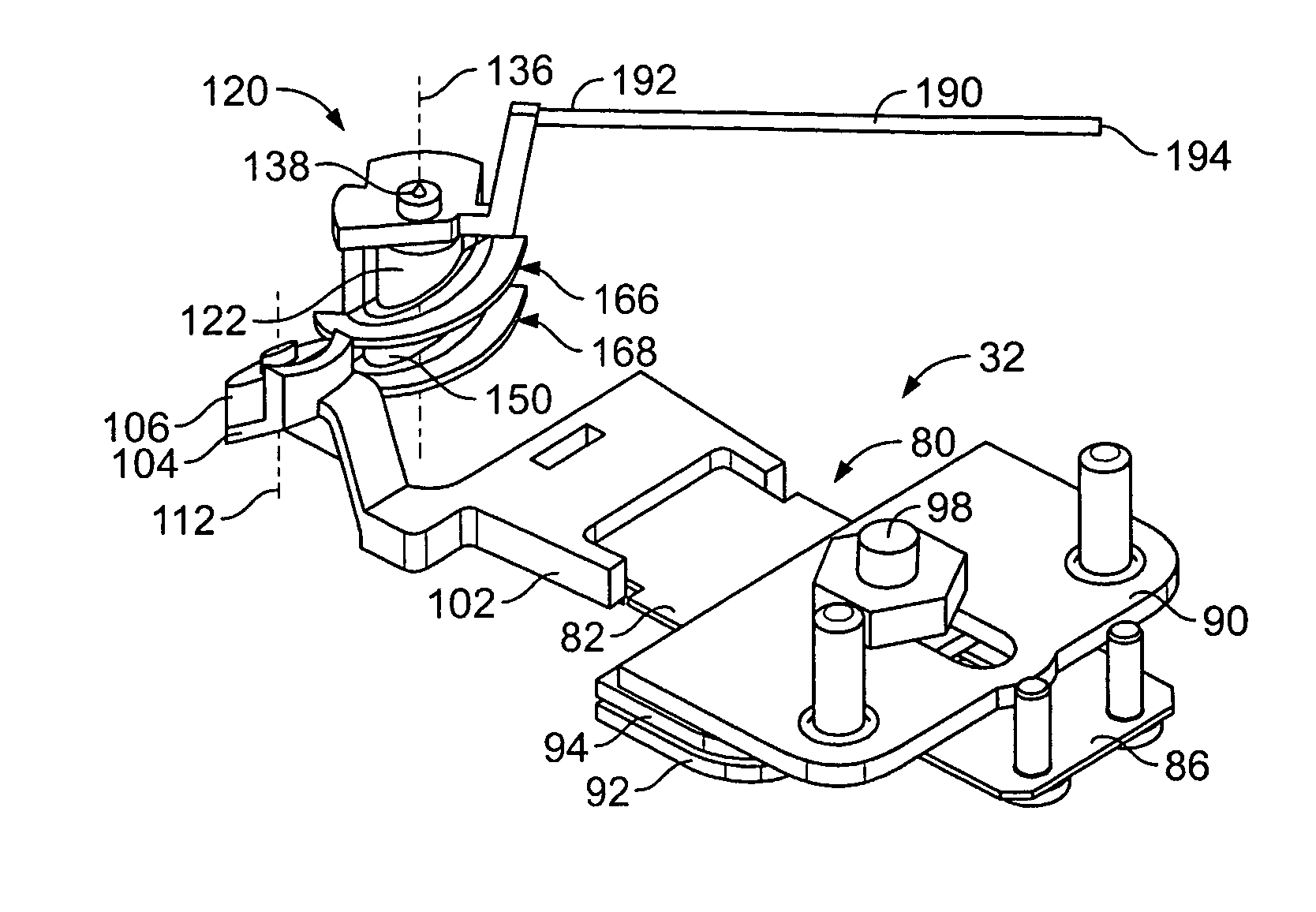
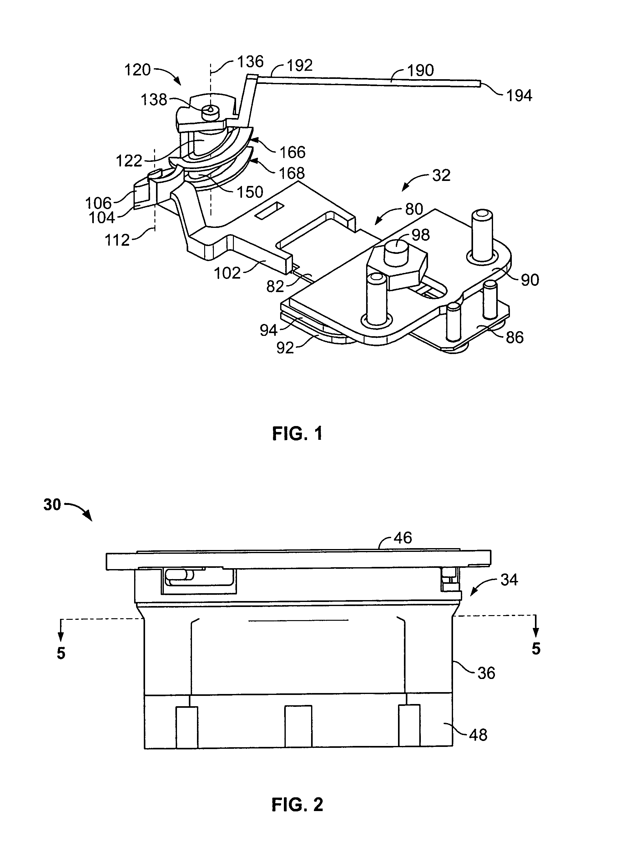
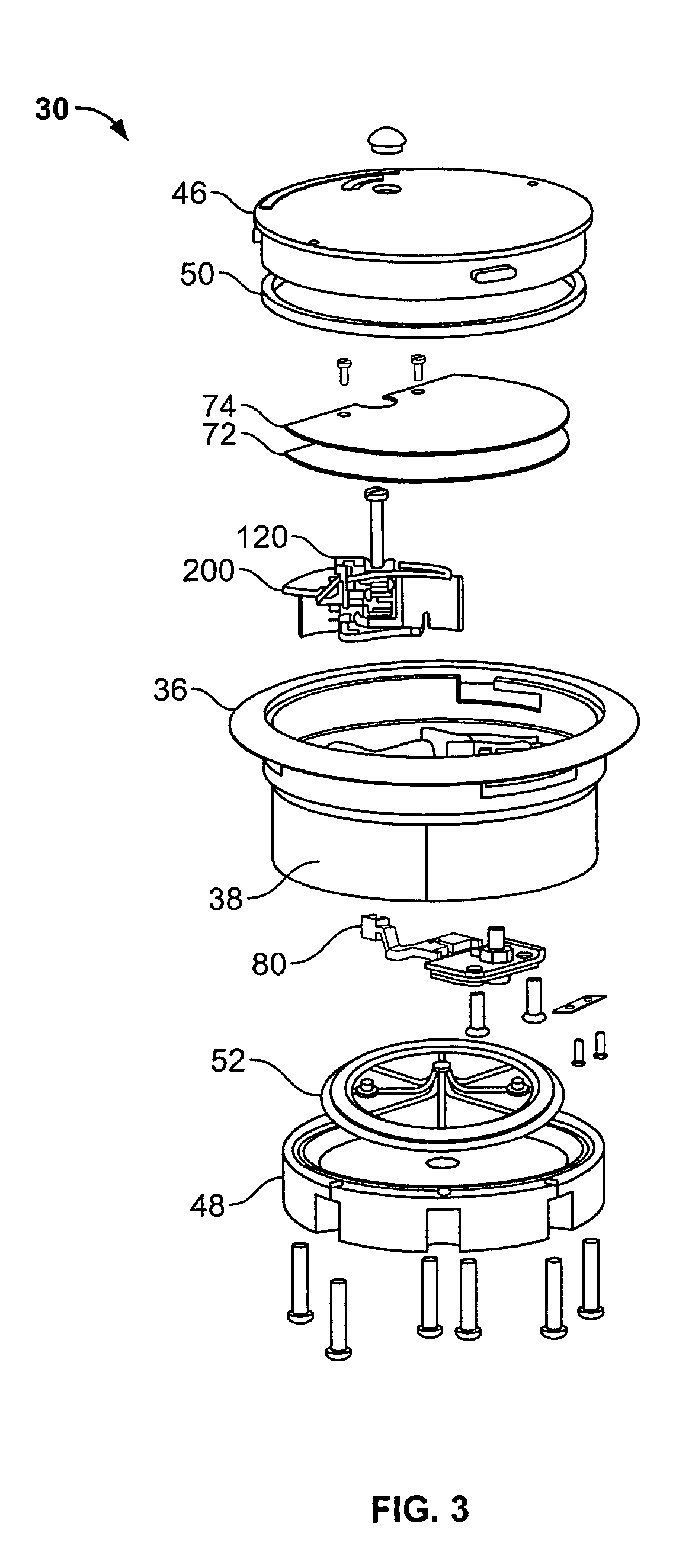
[0023]As shown in FIGS. 1 and 2, a gauge 30 includes a motion transmitting mechanism 32. The gauge 30 may be a pressure gauge adapted to sense and indicate a measured pressure which may be a differential in pressure between the pressure of a first fluid and the pressure of a second fluid. As shown in FIGS. 3 and 7, the gauge 30 includes an enclosure 34 having a housing 36. The housing 36 includes a circumferential side wall 38 that extends from a first end 40 to a second end 42. The housing 36 also includes an interior barrier wall 44 that is solid and non-perforate and that is integrally attached to the side wall 38. The enclosure 34 also includes a viewing cover 46 that is removably attached to the first end 40 of the side wall 38. The cover 46 may be formed from a clear see-through plastic material. The enclosure 34 also includes a back plate 48 that is removably attached to the second end 42 of the side wall 38. The housing 36, cover 46 and back plate 48 are all molded from a pl...


PUM

PropertyMeasurementUnit
angleaaaaaaaaaa
angleaaaaaaaaaa
magnetic fieldaaaaaaaaaa

Abstract

A gauge for indicating a measured variable such as pressure. The gauge includes a motion detection device including a drive magnet that is adapted to be moveable in response to changes in the variable. The pointer rotation device includes a pivot member, a power magnet coupled to the pivot member, and one or more director members located adjacent the power magnet. Each director member includes a generally helical flange. A pointer is coupled to the pointer rotation device. The director members and the power magnet form a magnetic field adapted to magnetically couple the pointer rotation device to the drive magnet. The pointer rotation device is adapted to rotate about a rotational axis. Movement of the drive magnet in response to changes in the variable rotates the pointer rotation device and the pointer about the rotational axis such that the pointer indicates the measured variable.

Description

RELATED APPLICATIONS[0001]This application claims the benefit of U.S. Provisional Application No. 60 / 592,214, filed Jul. 29, 2004.BACKGROUND OF THE INVENTION [0002]The present invention is directed to a gauge having a magnetically driven pointer rotation device that is adapted to detect and indicate the position of a drive magnet coupled to a pressure sensing flexible diaphragm, and in particular a pointer rotation device including a power magnet that creates a magnetic circuit with the drive magnet.[0003]Gauges, such as pressure gauges, include a flexible diaphragm that is located between a first fluid chamber and a second fluid chamber. A pointer assembly is often located in an indicator chamber of the gauge. The indicator chamber is separated from the fluid chambers by a separating wall that includes an aperture through which the pointer assembly is mechanically coupled to the diaphragm. In such a case, fluid within a fluid chamber is in contact with the pointer assembly. Mechani...

Claims


Application Information

Patent Timeline
Patent Type & Authority Patents(United States)
IPC IPC(8): G01L19/08
CPCG01D13/22G01L19/08G01L9/14G01L7/08
Inventor BUCHANAN, STEVEN O.
Owner DWYER INSTR
Why Eureka
Try Eureka