
Servo device for radio control

a technology of radio control and servo, which is applied in the direction of remote control toys, instruments, and gearing, etc., can solve the problems of reducing the accuracy of the torque transmission

Inactive Publication Date: 2007-10-23
FUTABA CORPORATION
View PDF8 Cites 18 Cited by
  • Summary
  • Abstract
  • Description
  • Claims
  • Application Information

AI Technical Summary

Benefits of technology

[0018]An object of the invention is to provide a servo horn capable of fine-adjusting a linkage rod, which links a servo device and an operation unit in an accurate positional relationship.
[0020]According to the present invention, the servo horn can be mounted at an arbitrary mounting angle with respect to the servo output shaft, without being limited by the serration mechanism of the servo output shaft. The angular adjustment mechanism comprises a serration structure formed on the periphery of the horn output shaft and in the inner wall of the shaft bore so that the mounting angle can be adjusted more finely with the serration pitch reduced.

Problems solved by technology

A failure of any type of adjustment causes an erroneous operation.
However, since the diameter of the output shaft of the servo device is small, the number of teeth is limited to reserve the torque transmission.
This fabrication work is burden to the user.
Moreover, there is a case that a new hole for readjustment cannot be formed close to the hole once formed, and the new hole has to be formed in a fresh servo horn.
Accordingly, the manipulators frequently trying the linkage adjustment, particularly, expert manipulators participating in competitions, cannot achieve not always satisfactory adjustment.

Method used


Image

  • Servo device for radio control
  • Servo device for radio control
  • Servo device for radio control

Examples


Embodiment Construction

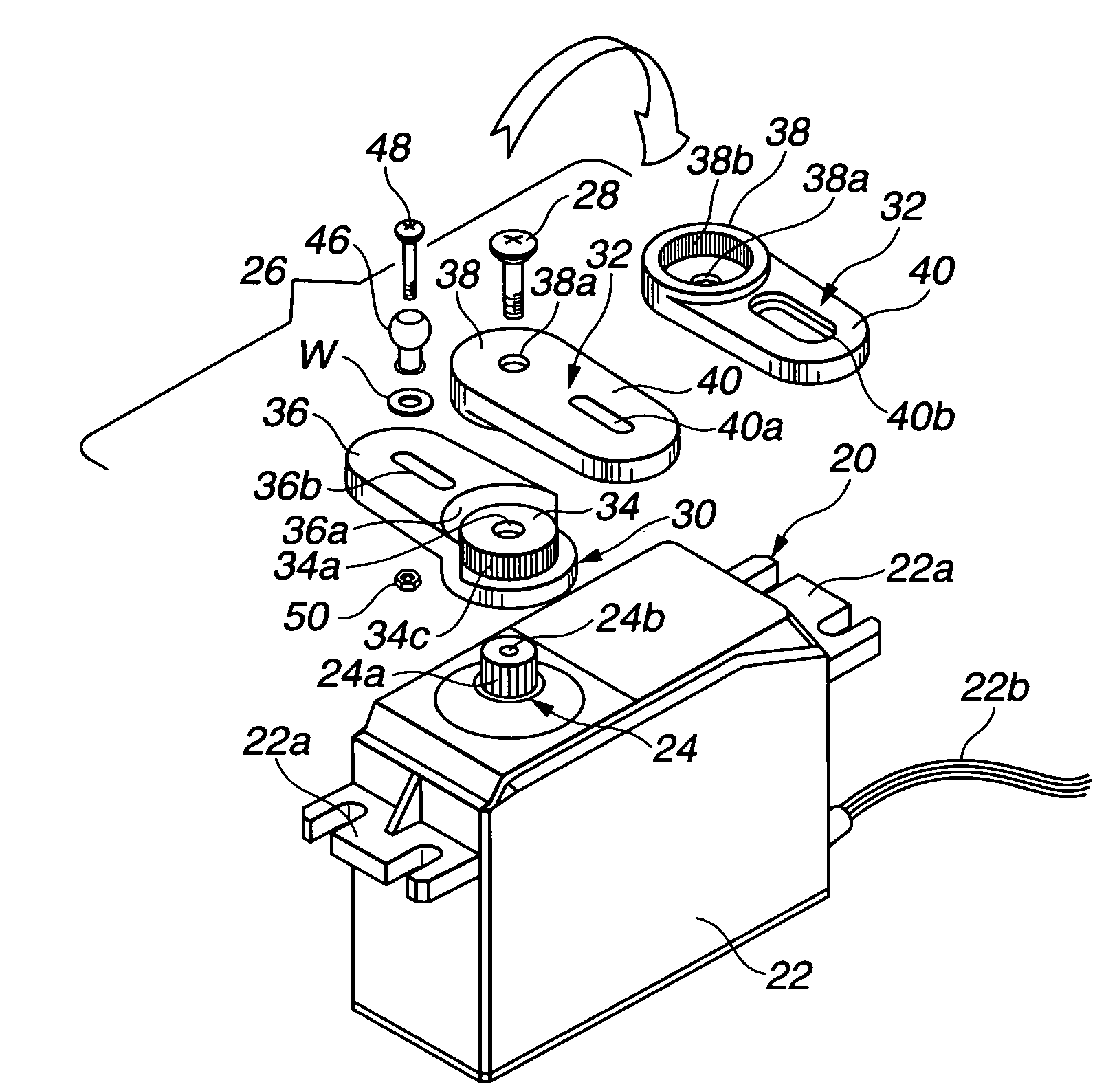
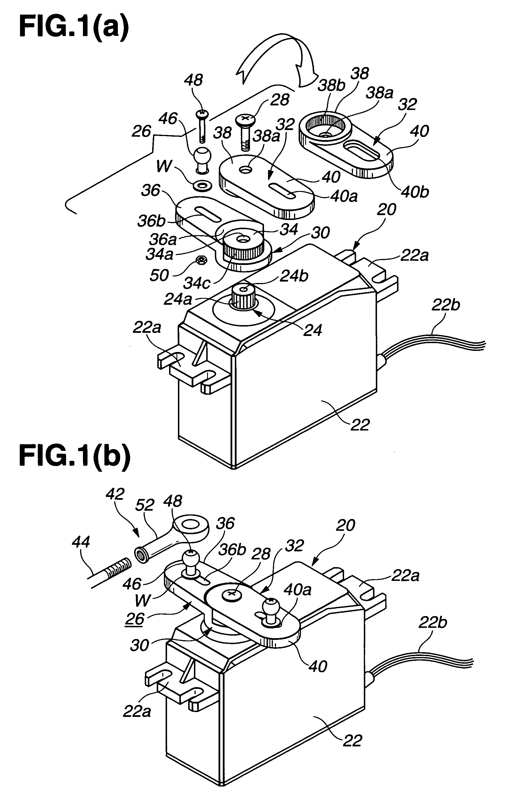
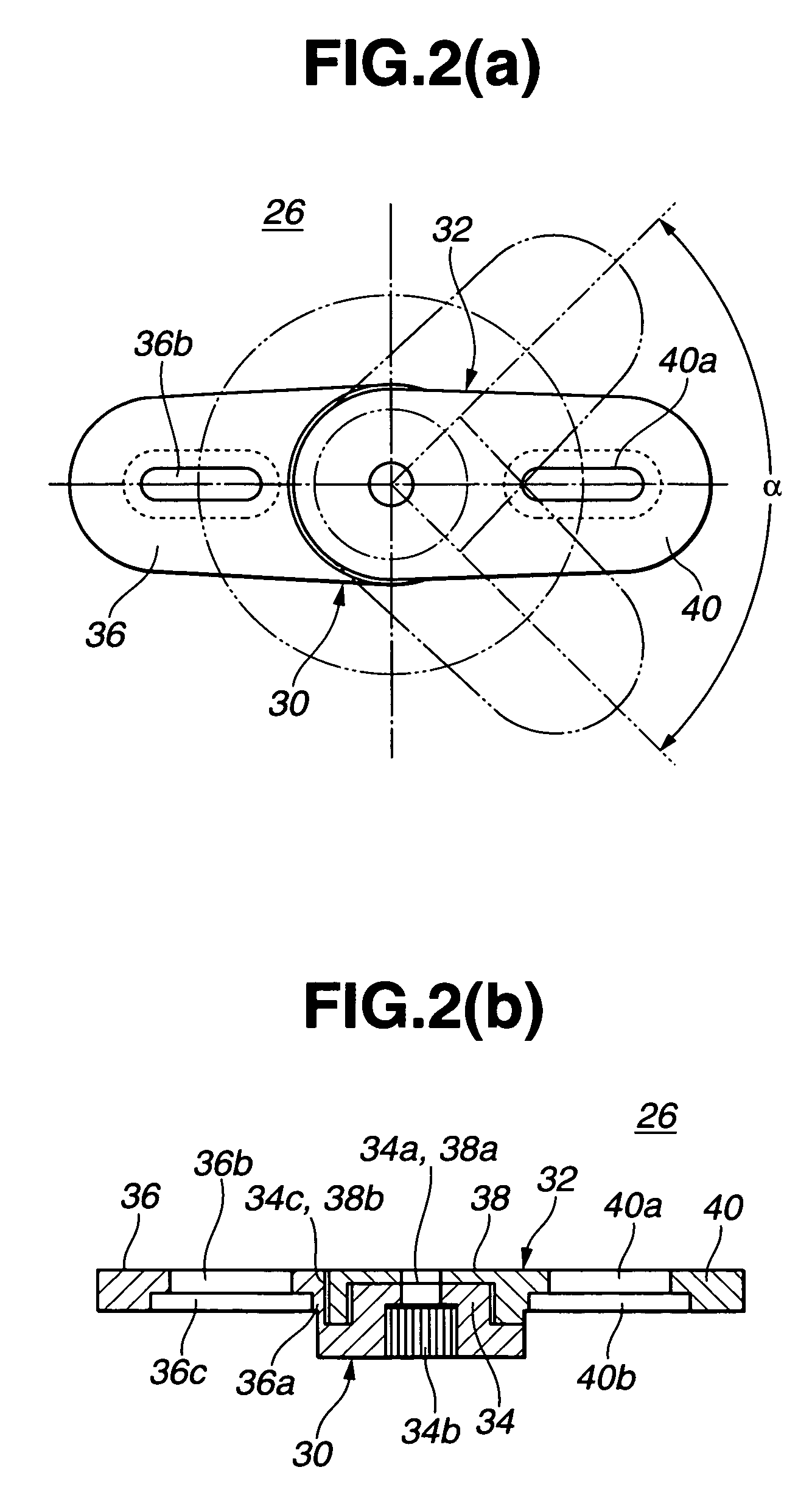
[0036]Preferred embodiments of the present invention will be described below by referring to the attached drawings. FIGS. 1 and 2 show a first embodiment of the present invention. FIGS. 1(a) and 1(b) show the entire structure of a servo device according to the present invention. FIGS. 2(a) and 2(b) show a sole servo horn.

[0037]Referring to FIGS. 1 and 2, the servo device comprises a servo motor 20 acting as a device body, a servo output shaft 24 protruding upward from the case 22 for the servo motor 20, and a two-arm-type servo horn 26 linked to the servo output shaft 24. The internal mechanism of the servo motor 20 is identical to that shown in FIG. 10 and hence the duplicate explanation will be omitted here.

[0038]Mount sections 22a are formed before and behind the case 22 to fix the servo device at an installation position with a wood screw or a metal screw. Lead wires 22b are derived from the rear of the case to connect it to the receiver.

[0039]A serration 24a is formed on the ou...


PUM


Abstract

A servo device for radio control fine-adjusts a linkage rod, which links the servo device and an operation unit, in an accurate positional relationship. The servo device includes a servo motor having a servo output shaft on which a serration is formed, and a servo horn having a shaft bore opened at the lower side thereof, the shaft bore having an inner wall on which an inner serration to be engaged to the servo output shaft is formed. The servo horn has a servo horn base from which the horn output shaft protrudes, the horn output shaft being above and coaxially to the shaft bore, an operation unit having a shaft bore engaging the horn output shaft, and an angular adjustment mechanism for linking the shaft bore of the operation unit to the horn output shaft so as to movably fix circumferentially and at an arbitrary angle.

Description

CROSS REFERENCE TO RELATED APPLICATION[0001]Not Applicable.STATEMENT REGARDING FEDERALLY SPONSORED RESEARCH[0002]Not Applicable.BACKGROUND OF THE INVENTION[0003]1. Field of the Invention[0004]The present invention relates generally to servo devices used for radio control (hereinafter referred to as R / C) devices, which remotely control miniatures, such as model helicopters, model aircrafts, model cars, model ships, and others, and unmanned operated industrial machines. Particularly, the present invention relates to an improvement of a servo horn, capable of fine-adjusting a rod for coupling a servo device and an operation unit in an accurate positional relationship.[0005]2. Description of the Prior Art[0006]Radio steering servo motors for miniatures or servo devices for radio control are well known (refer to Japanese Utility Model Publication No. 53-43277 and Japanese Utility Model Publication No. 2-32319). Basically, as shown in FIGS. 9 and 10, the servomotor includes a servo circui...

Claims


Application Information

Patent Timeline
Patent Type & Authority Patents(United States)
IPC IPC(8): H01Q3/08A63H29/22A63H29/24A63H30/04H02K7/116H02K7/14H02K11/00
CPCA63H29/22A63H29/24A63H30/04H02K7/116H02K11/0078Y10T403/7026H02K11/0036Y10T74/22H02K7/14H02K11/23H02K11/35
Inventor JINNO, EIJIDOBASHI, YUKIHIRO
Owner FUTABA CORPORATION
Learn More