Lifting device

a lifting device and cable technology, applied in the direction of lifting equipment, load-engaging elements, transportation and packaging, etc., can solve the problems of increasing wear and tear of hoisting cables, and achieve the effect of reducing maintenance work and prolonging the expected lifetim

Active Publication Date: 2007-10-23
HANS KUENZ GMBH +1
View PDF13 Cites 52 Cited by
  • Summary
  • Abstract
  • Description
  • Claims
  • Application Information

AI Technical Summary

Benefits of technology

[0011]It is the primary object of the invention to provide an improved lifting device of the type mentioned in the beginning in which the maintenance work is reduced and the hoisting cables have a longer expected lifetime.
[0013]Accordingly, in the lifting device of the invention a hoist is provided for the two longitudinal cable pairs on one hand and a hoist which is mechanically separate from the latter, i.e., which is not mechanically coupled with the hoist for the two longitudinal cable pairs, is provided for the two transverse cable pairs. Each of the two hoists has its own driving motor, and the two driving motors are controlled by a common control device. By suitably controlling the two driving motors, substantially identical cable tensions can be achieved for all hoisting cables without requiring an exact adjustment of the hoisting cable itself for this purpose. In this way, the expected lifetime of the hoisting cables can be substantially increased and maintenance work can be substantially reduced.
[0014]In an advantageous embodiment form of the invention, each of the two hoists has separate cable drums for the two cables of the cable pairs associated with the respective hoist. The separate cable drums of a respective hoist are mechanically coupled and run synchronous with one another. This does away with the need for deflection pulleys for four of the hoisting cables which would increase wear on the hoisting cables running over them.

Problems solved by technology

This does away with the need for deflection pulleys for four of the hoisting cables which would increase wear on the hoisting cables running over them.

Method used


Image

  • Lifting device
  • Lifting device
  • Lifting device

Examples


Embodiment Construction

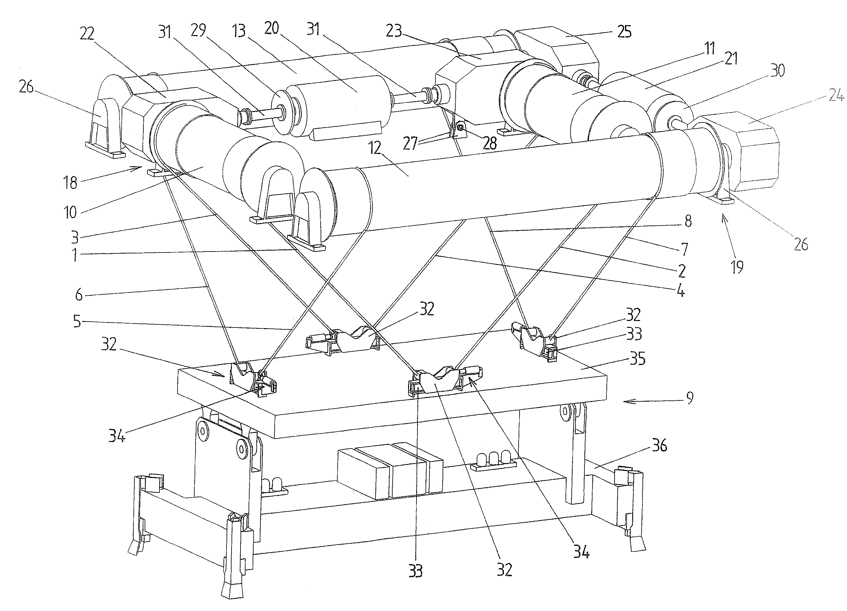
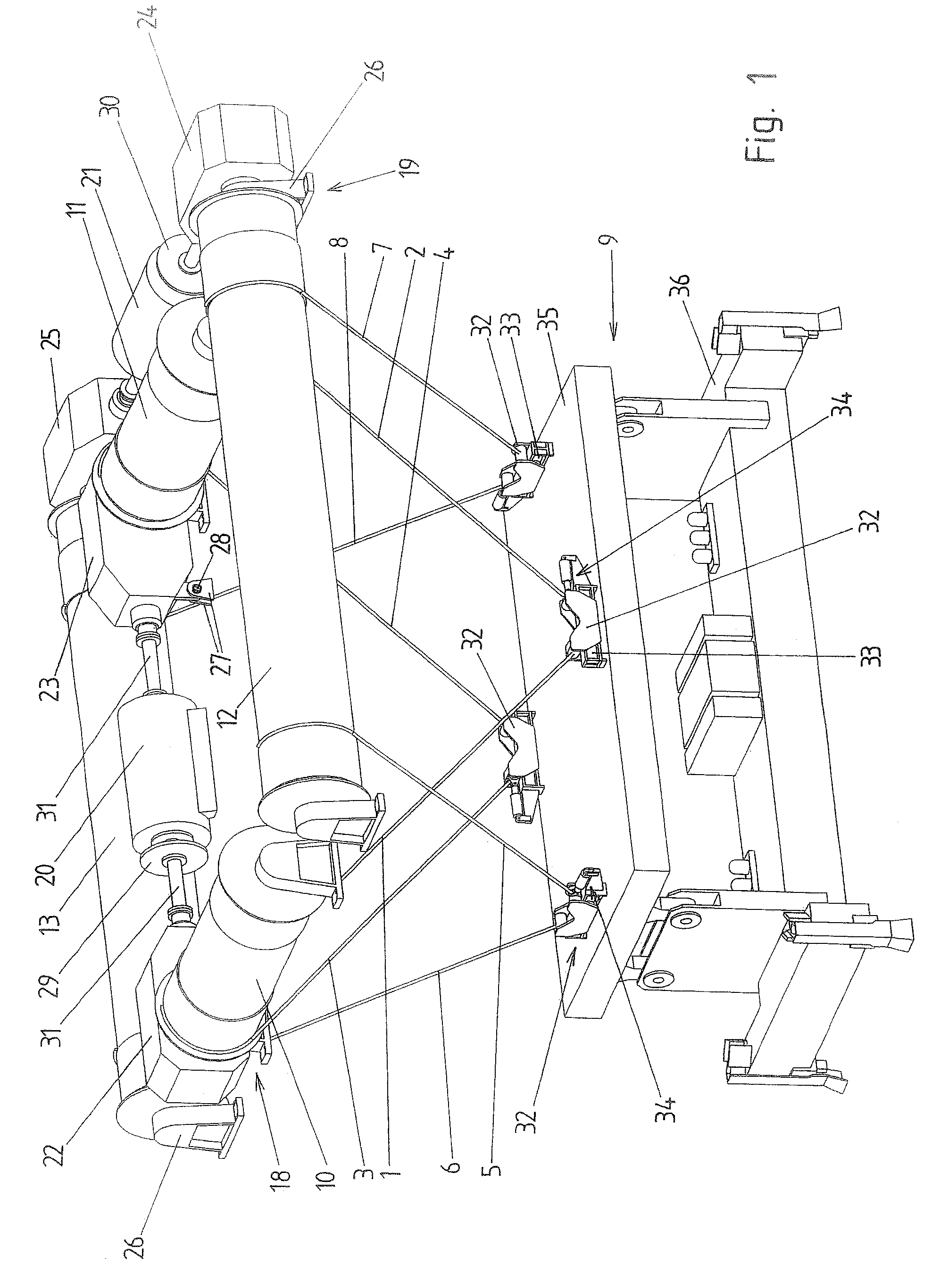
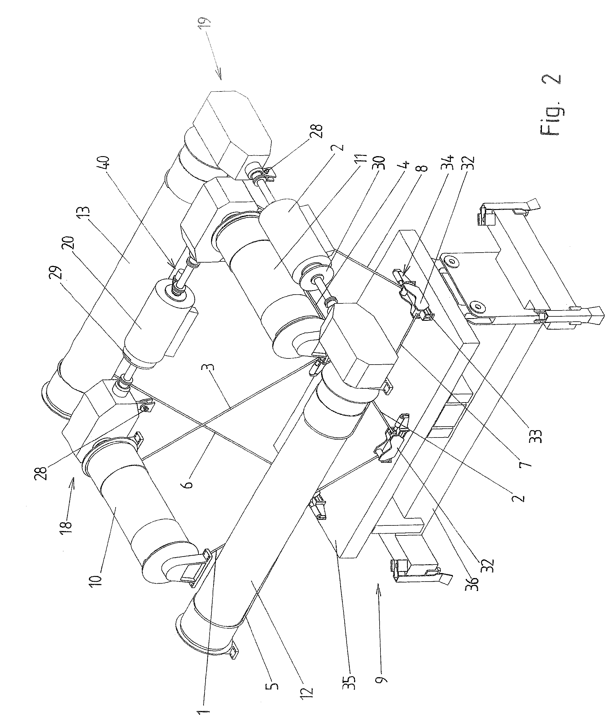
[0020]An embodiment example of a lifting device according to the invention is shown schematically in the drawings. A lifting device of this kind can be used particularly in a crane, e.g., a container crane.

[0021]The lifting device comprises eight hoisting cables 1 to 8 which are arranged in pairs in a V-shaped manner relative to one another. Hoisting cables 1 to 8 of a respective pair of cables run apart in an upward direction. At their bottom ends, the hoisting cables 1 to 8 are connected to a load suspension apparatus 9. To lift and lower the load suspension apparatus 9, the hoisting cables 1 to 8, whose top ends are connected to cable drums 10 to 13, can be wound on to and wound off from these cable drums 10 to 13 to varying lengths.

[0022]The free lengths of the hoisting cables 1, 2 and 3, 4, respectively, of the two longitudinal cable pairs lie in longitudinal planes 14, 15 which are at a distance from one another. The free lengths of the hoisting cables 5, 6 and 7, 8, respectiv...


PUM


Abstract

A lifting device comprises four pairs of hoisting cables arranged in a V-shape relative to one another for lifting and lowering a load suspension apparatus at which they engage and which are taken off from drivable cable drums. The free lengths of the hoisting cables of two longitudinal pairs of cables lie in longitudinal planes which are located at a distance from one another, and the free lengths of the hoisting cables of two transverse pairs of cables lie in transverse planes which are located at a distance from one another and which extend at right angles to the longitudinal planes. Two mechanically separate hoists are provided for the hoisting cables of the two longitudinal cable pairs and for the hoisting cables of the two transverse cable pairs, each of the hoists is drivable by its own driving motor, and the driving motors are controlled by a common control device.

Description

CROSS-REFERENCE TO RELATED APPLICATION[0001]This application claims priority of German Application No. 10 2006 000 490.4, filed Jan. 12, 2006, the complete disclosure of which is hereby incorporated by reference.BACKGROUND OF THE INVENTION[0002]a) Field of the Invention[0003]The invention is directed to a lifting device with four pairs of hoisting cables arranged in a V-shape relative to one another for lifting and lowering a load suspension apparatus at which they engage and which are taken off from drivable cable drums, the free lengths of the hoisting cables of two longitudinal pairs of cables lie in longitudinal planes which are located at a distance from one another, and the free lengths of the hoisting cables of two transverse pairs of cables lie in transverse planes which are located at a distance from one another and which extend at right angles to the longitudinal planes.[0004]b) Description of the Related Art[0005]A known lifting device of the type mentioned above is used ...

Claims


Application Information

Patent Timeline
Patent Type & Authority Patents(United States)
IPC IPC(8): B66D1/26
CPCB66C13/06
Inventor LERCHENMUELLER, PETERFITZ, JOSEF
Owner HANS KUENZ GMBH
Why Eureka
Try Eureka