Centralized control device for controlling the application of voltage to a load provided with a power factor correction capacitor

a technology of power factor correction and centralized control, which is applied in the direction of furniture parts, movable shelf cabinets, cabinets, etc., can solve the problems of hindering the use of supply voltage regulators, affecting the use of control devices, and affecting the efficiency of control devices

Inactive Publication Date: 2007-10-30
REVERBERI ENETEC
View PDF3 Cites 46 Cited by
  • Summary
  • Abstract
  • Description
  • Claims
  • Application Information

AI Technical Summary

Benefits of technology

[0007]It is an object of the present invention to overcome the above drawbacks by providing a centralized control device for controlling the voltage applied to a load having power factor correction capacitors, in particular, for use in lighting engineering applications, which control device is improved and performs better than prior art solutions.

Problems solved by technology

In the instance of electromagnetic controllers, these restrictions are basically ascribable to the dimensions and weights of the transformers; a further technical restriction is due to the limited number of applicable sockets connected to a transformer, hindering in practice the possibility of controlling the supply voltage output with a higher precision than a few percentage points.
Both solutions require sudden changes in the voltage applied to the load, which hinder their use in the case of improved loads, i.e. loads fitted with power factor optimizing capacitors, which is a usual condition for high performance lamps with very low power factors.
The main disadvantage of U.S. Pat. No. 4,456,855 is that it does not take into consideration the different behaviour of loads of different nature, thus it does not permit a good regulation strategy.

Method used


Image

  • Centralized control device for controlling the application of voltage to a load provided with a power factor correction capacitor
  • Centralized control device for controlling the application of voltage to a load provided with a power factor correction capacitor
  • Centralized control device for controlling the application of voltage to a load provided with a power factor correction capacitor

Examples


Embodiment Construction

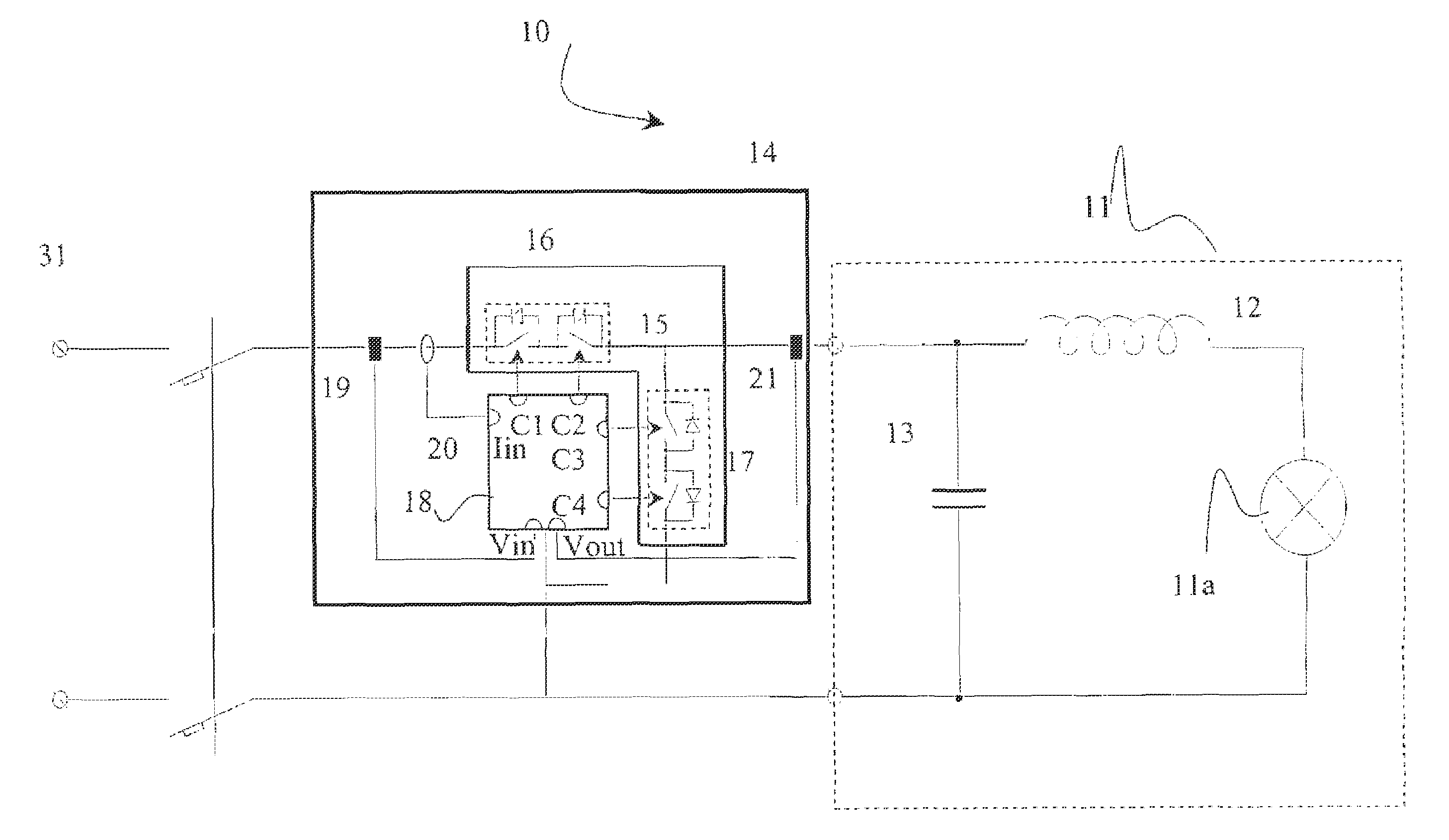
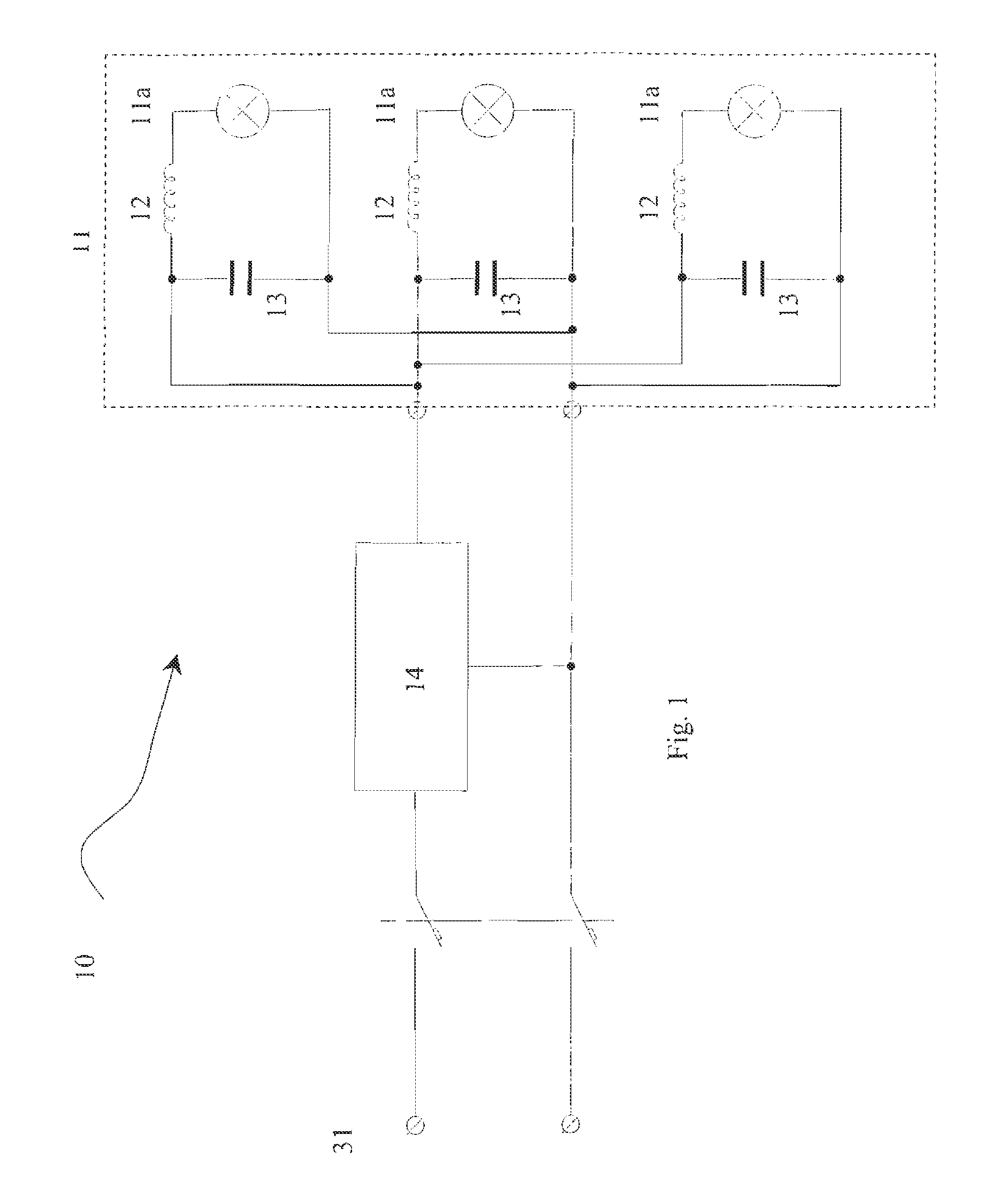
[0015]FIG. 1 illustrates a lighting system 10 having power supply terminals 31 connected to a supply network, not illustrated. This lighting system includes a load 11, which is modelled and represented by a variable number of discharge lamps 11a fitted with a feeder 12 and power factor correction capacitor 13. The load 11 is supplied by a single-phase alternating voltage through the terminals 31.

[0016]The lighting system 10 comprises an electronic power device 14 located between the terminals 31 and the load 11 for controlling and choking the power supplied to said load 11, according to requirements.

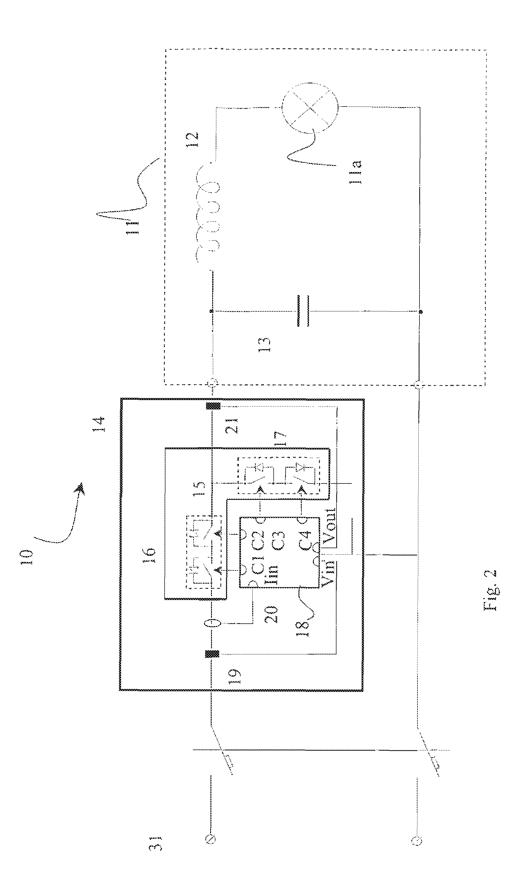
[0017]In FIG. 2, where the lighting system 10 of FIG. 1 is better detailed, the load consisting of multiple lamps 11a is converted to an equivalent lamp also indicated with 11a, for simplicity's sake.

[0018]According to the present invention, the electronic power device 14 located between the terminals 31 and the load 11 consists substantially of an array converter 15, comprising two bi-d...


PUM


Abstract

A centralized device for supply voltage control of a load with power factor correction condensers for lighting engineering applications has an array converter for obtaining a portion of power, with a plurality of switches located between the network sinusoidal supply and the load. The centralized device has controlling and regulating means for managing both the activation and deactivation states of the switches of the array converter so as to avoid sudden voltage changes across the load and provide for control of the load voltage.

Description

BACKGROUND OF THE INVENTION[0001]The present invention relates to a centralized controller for controlling the voltage applied to a load having power factor correction capacitors, in particular, for lighting engineering applications. The controller has a power regulator in the form of a converter, which includes a plurality of switching devices located between the AC power supply network or grid and the load.[0002]Street lighting systems, or those systems provided for large sport, industrial, commercial or educational areas, should be able to change their lighting power depending on their real utilization requirements, so as to obtain a considerable saving of electric power and extend lamps life.[0003]Common systems for reducing the lighting power are based on electromagnetic devices, such as transformers with sockets or VARIAC, or on the use of electronic controllers. Both cases are subject to utilization restrictions. In the instance of electromagnetic controllers, these restricti...

Claims


Application Information

Patent Timeline
Patent Type & Authority Patents(United States)
IPC IPC(8): H05B37/00H02M5/293H05B39/04H05B41/392
CPCH02M5/293H05B41/3924H05B39/048
Inventor NUMEROLI, RENATOPORTA, LUCA
Owner REVERBERI ENETEC
Why Eureka
Try Eureka