Electric compressor control device

a control device and compressor technology, applied in the direction of electric devices, process and machine control, motor/generator/converter stoppers, etc., can solve the problems of inability to ensure communication reliability, long wiring length in the actual circuit construction, and large circuit size, so as to improve communication reliability and stability of the control device as a whole.

Active Publication Date: 2010-07-29
SANDEN CORP
View PDF6 Cites 6 Cited by
  • Summary
  • Abstract
  • Description
  • Claims
  • Application Information

AI Technical Summary

Benefits of technology

[0017]In the electric compressor control device according to the present invention, an existing insulation element can be used for an insulation boundary part between low-voltage region and the high-voltage region, the low-speed communication between the communication microcontroller which receives a signal from the high-speed communication bus and the control microcontroller can be ensured stably, and predetermined power source voltage can be surely supplied into both of the communication microcontroller and the control microcontroller, so that stable operation can be ensured and the communication reliability as a whole control device can be greatly improved.
[0018]FIG. 1 is a schematic circuit diagram of the electric compressor control device according to an embodiment of the present invention.
[0019]FIG. 2 is a schematic circuit diagram of a conventional electric compressor control device.

Problems solved by technology

When those high-speed communication buses are employed, high-speed communication bus 107 and control microcontroller 109 are directly connected by photo-coupler 108 in an conventional construction as shown in FIG. 2, however, because the present photo-couplers are not suitable for high-speed communication, there is a problem that the response lag of photo-coupler 108 is generated to cause the communication lag, so that it is difficult to ensure the communication reliability.
However, in the construction disclosed in Patent document 1, because the power source voltage for the control microcontroller is designed to be supplied from a high-voltage power source (Namely, power source 101 in FIG. 2), if the high-voltage power source is unconnected the low-speed communication from the communication microcontroller to the control microcontroller cannot be performed and a trouble may be caused.
In addition, because the power source voltage for the control microcontroller is taken out of the high-voltage power source at the inverter side, the length of wiring in an actual circuit construction becomes long and the circuit size becomes larger, and a voltage check circuit, etc., to stabilize the supply voltage is required separately because there is no guarantee that a predetermined voltage can be stably supplied to the control microcontroller.
Therefore, there is a fear that the movement of the control microcontroller is not sufficiently stable and that the communication of the signal is not sufficiently reliable, consequently.

Method used


Image

  • Electric compressor control device
  • Electric compressor control device
  • Electric compressor control device

Examples


Embodiment Construction

[0035]Hereinafter, desirable embodiments will be explained referring to figures.

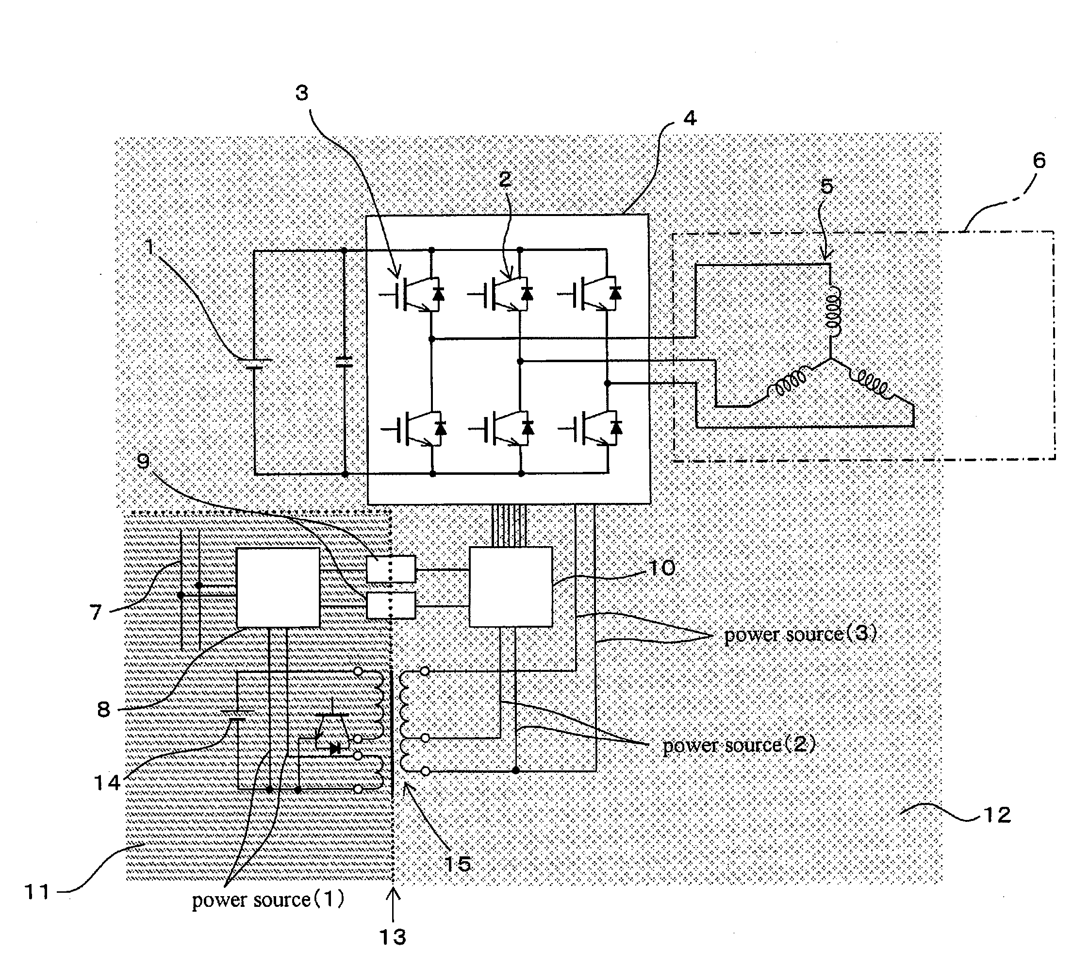
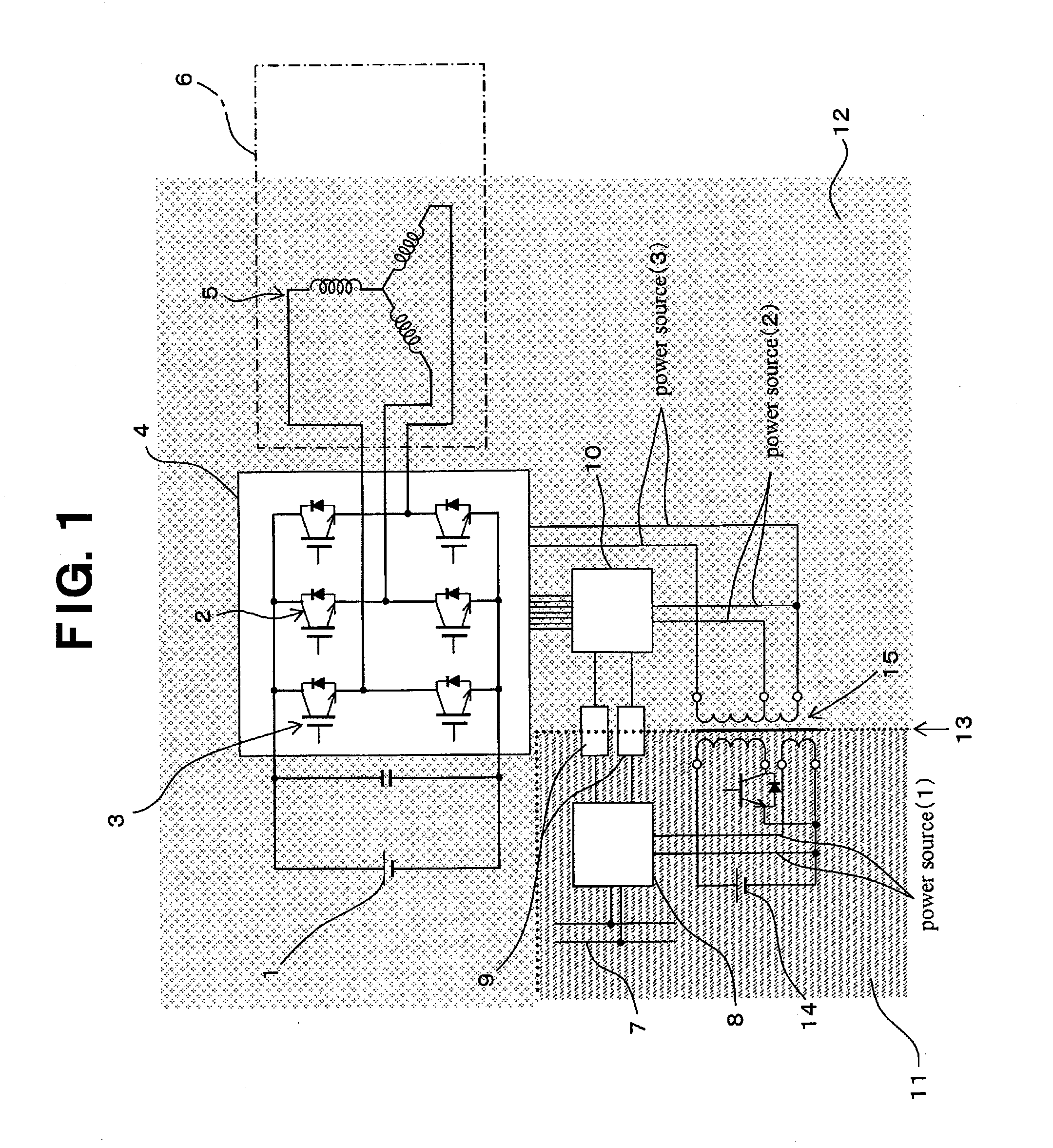
[0036]FIG. 1 shows an electric compressor control device according to an embodiment of the present invention, and specifically shows an example of a control device for an electric compressor which is provided in a refrigeration cycle of an air conditioning system for vehicles. In FIG. 1, symbol 1 implies a high-voltage direct current power source, such as a high-voltage battery mounted in a vehicle. A direct current supplied from high-voltage power source 1 is converted by inverter 4 having multiple switching elements 2 and gate driving circuit 3 into a pseudo alternating current, such as 3 phase alternating current in this embodiment, and the alternating current is supplied into motor 5 so that electric compressor 6 with built-in motor 5 is driven. Electric compressor 6 includes a compressor having only motor 5 as a drive source as well as a hybrid type compressor having inside the compressor a first co...


PUM


Abstract

An electric compressor control device includes: an inverter for electric compressor motor; a communication microcontroller arranged in a low-voltage region for transmission of an instruction signal via a high-speed communication bus; and a control microcontroller arranged in a high-voltage region and connected to the communication microcontroller via an insulation element for transmitting the instruction signal from the communication microcomputer as an inverter control signal to the inverter. The power voltage of the communication microcomputer is supplied from a low-voltage power source. The voltage from the low-voltage power source is transformed via a transformer and supplied as a power voltage of the control microcontroller. Thus, it is possible to use the existing insulation element at an insulation boundary between the low-voltage region and the high-voltage region so as to surely supply a predetermined power voltage to the microcontroller for controlling the inverter, thereby improving the communication reliability of the entire control device.

Description

TECHNICAL FIELD OF THE INVENTION[0001]The present invention relates to an electric compressor control device, and specifically, relates to an electric compressor control device which is suitable as an inverter control device for an electric compressor used in an air conditioning system for vehicles.BACKGROUND ART OF THE INVENTION[0002]Such a technology for a drive control of a motor of an electric compressor used in an air conditioning system for vehicles, for example, is known that a direct current supplied from a DC power source, such as high-voltage power source, is transformed by an inverter having multiple switching elements and a gate driving circuit into a pseudo alternating electric current, such as a 3-phase AC current, and that pseudo alternating electric current is applied to a motor for controlling the motor. For controlling that inverter, a control microcontroller is used, for example, and an instruction signal from the upper control unit is sent to the control microcon...

Claims


Application Information

Patent Timeline
Patent Type & Authority Applications(United States)
IPC IPC(8): H02P23/00B60L1/00B60H1/32F04B49/06H02M3/28H02M7/48H02P23/07H02P25/022H02P27/06
CPCH02M7/53875H02P27/14H02M2001/0006H02M1/0006
Inventor SHIBUYA, MAKOTO
Owner SANDEN CORP
Why Eureka
Try Eureka