Short reverse rotation of compressor at startup

a compressor and startup technology, applied in the direction of positive displacement liquid engines, piston pumps, lighting and heating apparatus, etc., can solve the problems of unfavorable preheated oil/refrigerant mixture in the oil sump, unfavorable preheating effect, and often shutting down of the container refrigeration system

Inactive Publication Date: 2007-11-06
CARRIER CORP
View PDF19 Cites 23 Cited by
  • Summary
  • Abstract
  • Description
  • Claims
  • Application Information

AI Technical Summary

Benefits of technology

[0011]Additional beneficial boiling off of refrigerant takes place as the oil / refrigerant mixture has been agitated by the electric motor rotor and rotor counterweight, rotating in the oil / refrigerant mixture. After a short period of time reverse rotation is stopped, and the motor is rotated in a forward direction and normal compression begins. However, the oil is now preheated and there is less liquid refrigerant in the oil.
[0012]The invention applies to compressors that have a rotary electric motor. In a most preferred embodiment of this invention, the compressor is a scroll compressor. In an alternate embodiment, the invention is used as a screw compressor. In addition, the present invention is most preferably used on an intermodal container refrigerant system. In such systems large fans mask any undesirable noise from the reverse rotation.

Problems solved by technology

The presence of the unpreheated oil / refrigerant mixture in the oil sump has undesirable effects.
The problem is particularly acute in refrigerant systems for intermodal transport, here refrigeration takes place in large containers used to transport fruit or other food products over long distances.
Thus, during its life cycle a container refrigeration system may often be shut down for long periods of time.
The problem can become especially severe during cold starts.
This is undesirable because on startup it can result in liquid refrigerant passing through the scroll elements.
This can result in bearing and scroll element damage.
Also oil dilution by the refrigerant may lead to lower lubricant viscosity, which is also detrimental to bearing life.
However, crank-case heaters require a long time to heat the oil and refrigerant mixture.
Thus, the heaters must be turned on for a relatively long period of time before the compressor can be started.
In addition, a crank-case heater is relatively expensive, and presents its own reliability problems.

Method used


Image

  • Short reverse rotation of compressor at startup
  • Short reverse rotation of compressor at startup
  • Short reverse rotation of compressor at startup

Examples


Embodiment Construction

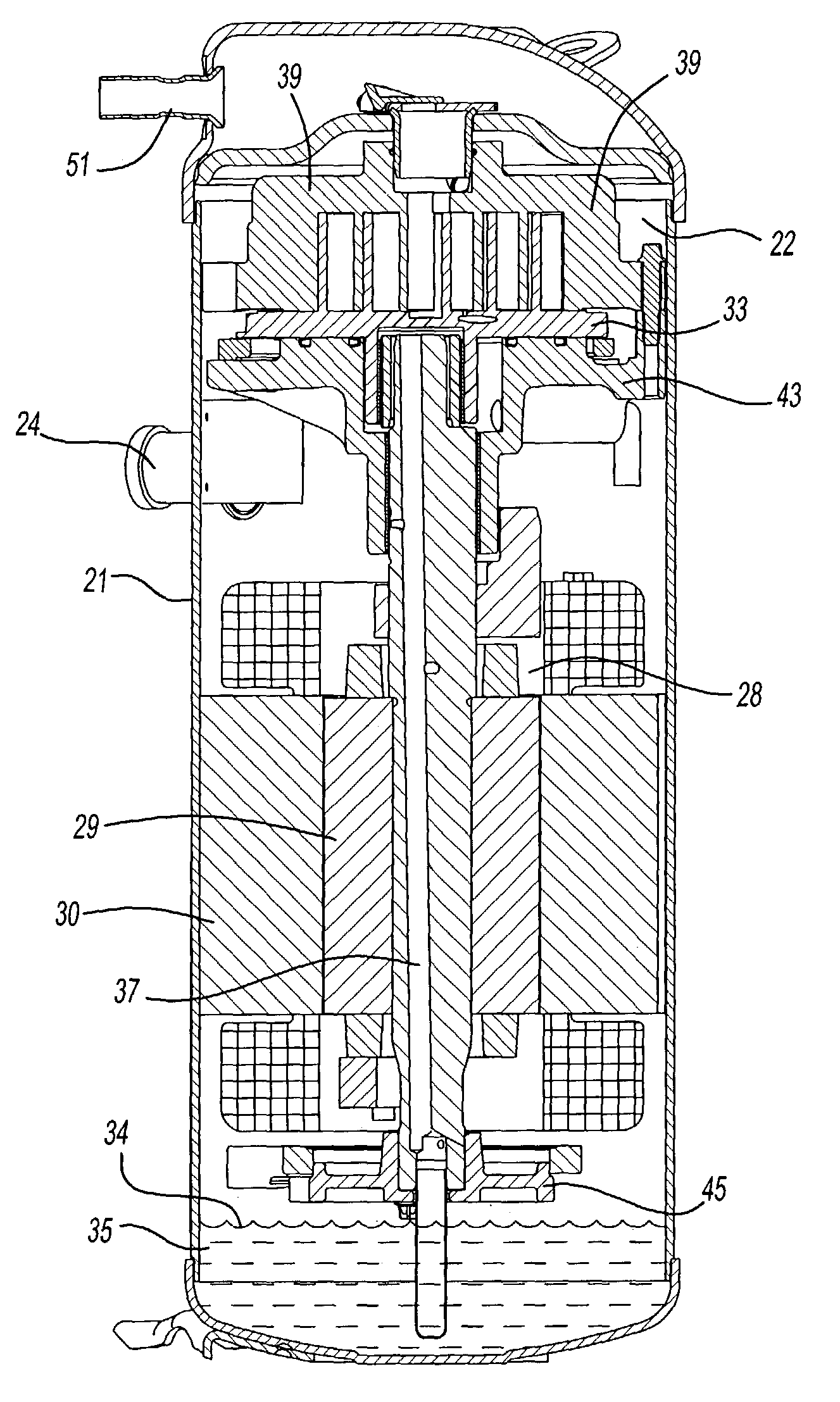
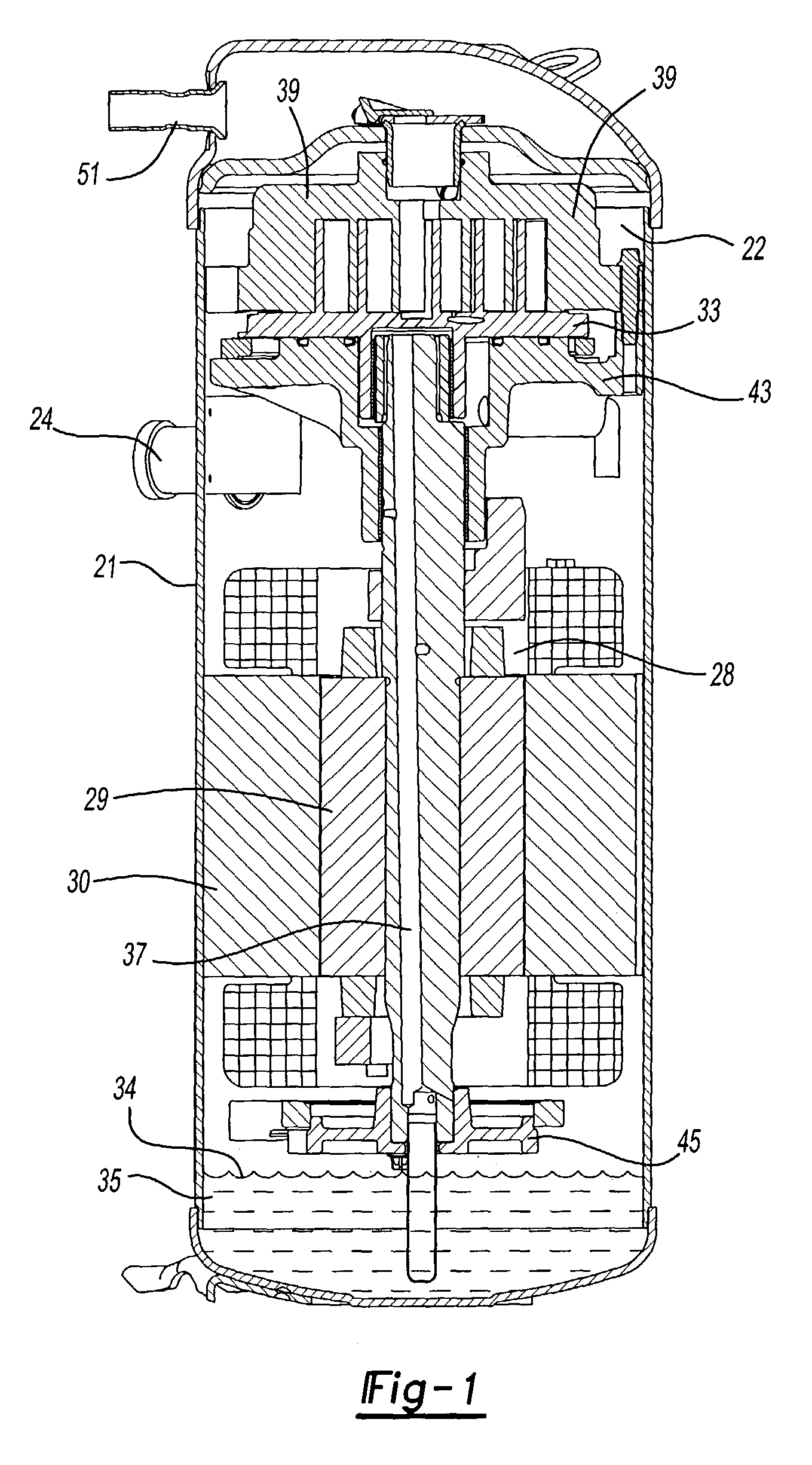
[0017]FIG. 1 shows a compressor 20 for practicing the present invention. As shown, a sealed compressor shell 21 receives a compressor pump unit 22 consisting of fixed scroll 39, orbiting scroll 33, and crankcase 5. An outlet 26 is formed at a location sealed from the inlet 24. A motor 28 is positioned in the sealed compressor shell 21, and has its rotor 29 spaced from its stator 30. The motor drives a shaft 32 which in turn drives the orbiting scroll 33 of a scroll compressor.

[0018]As shown, oil 34 fills the oil sump 35 and the bottom of rotor 29 and shaft 32 rotate within the oil sump. As known, oil travels up a passage 37 within the shaft 32 to lubricate bearings, and fixed 39 and orbiting scroll 33. The fixed scroll is supported by crankcase 43 and the shaft is supported axially by lower bearing ring 45.

[0019]During normal operation, the rotor and shaft rotate in a forward direction and the scroll compressor compresses fluid. Fluid enters the compressor shell 21 through inlet 24 ...


PUM


Abstract

In a method of operating a scroll or screw compressor at startup, the compressor is rotated in reverse for a brief period of time. The compressor is of a type that does not compress liquid when rotated in reverse. The purpose is to boil off the liquid refrigerant from the oil by heating and agitating the mixture of oil and refrigerant in the oil sump. This results in much more benign forward start as no refrigerant is drawn into the scroll compressor pump and the amount of oil pumped out of the compressor on start up is minimized. Also, the viscosity of oil is increased and lubrication of the bearings is improved. After a short period of time reverse rotation is stopped and the compressor can begin to be driven in the forward direction.

Description

[0001]This application is a continuation-in-part of U.S. patent application Ser. No. 09 / 092,368 filed on Jun. 5, 1998.BACKGROUND OF THE INVENTION [0002]This invention relates to a unique method of minimizing the detrimental effect of scroll or screw compressors flooded starts.[0003]Scroll compressors are widely utilized in refrigerant compressor operation. One known type of scroll compressor includes compression elements and an electric motor housed within a sealed compressor shell. A quantity of lubricant is also received in the compressor shell. In such compressors, the refrigerant passes over the motor on its way to the inlet of the compression elements, cooling the motor.[0004]In a scroll compressor a pair of scroll members have wraps which interfit with each other to define compression chambers. When rotated in a forward direction, a normal compression process occurs in which refrigerant is trapped between the wraps and compressed towards a discharge port.[0005]At startup the o...

Claims


Application Information

Patent Timeline
Patent Type & Authority Patents(United States)
IPC IPC(8): F04B19/24F04C18/02F04C18/16F04C23/00F04C28/06F04C28/28F04C29/02
CPCF04C18/0215F04C18/16F04C23/008F04C28/06F04C29/02F04C28/28F04C2270/701F04C29/023F25B2500/26
Inventor LIFSON, ALEXANDER
Owner CARRIER CORP
Why Eureka
Try Eureka