Fusible link and battery fuse unit containing the fusible link

a technology of fuse unit and fuse, which is applied in the direction of contacts, electrical equipment, cell components, etc., can solve the problems of reducing the reliability of fuse blowing, affecting the efficiency of battery fuse unit, and unable to efficiently contain fuse, etc., to achieve efficient containment, reduce the number of parts, and thin and compact battery fuse unit

Inactive Publication Date: 2007-11-06
SUMITOMO WIRING SYST LTD
View PDF9 Cites 15 Cited by
  • Summary
  • Abstract
  • Description
  • Claims
  • Application Information

AI Technical Summary

Benefits of technology

[0012]According to the above construction, the resin section encloses the fusible section so that a cavity is defined around the fusible section and the coupling portions between the fusible section and the input and output side connecting-sections are molded in the resin section. Consequently, it is possible to reinforce the fusible section, to protect it from being interfered with external components, and to blow out the fusible section when overcurrent greater than a setting value flows in the fusible section.
[0025]Since the battery fuse unit in the second aspect of various exemplary embodiments of the invention contains the input side connecting-section of the fusible link directly connected to the battery terminal in the casing, it is possible to make a compact and thin battery fuse unit and furthermore to reduce the number of parts. Because the unit is mounted on the battery box directly, it is not necessary to dispose another fuse box and to effectively utilize a restricted space of a vehicle.

Problems solved by technology

When the fusible section is blown out, the fusible section cannot be viewed from outside and may generate smoke due to heat generation, because the fusible section is embedded in the resin casing.
This will lower reliability in fuse blowing.
Because the above fuse cannot be directly connected to the battery terminal and an input terminal section and an output terminal section are disposed on the opposite ends of the fusible section, when the input terminal section is connected through an intermediate terminal and the output terminal section is connected to an electrical cable, the fuse cannot be efficiently arranged in a casing.

Method used


Image

  • Fusible link and battery fuse unit containing the fusible link
  • Fusible link and battery fuse unit containing the fusible link
  • Fusible link and battery fuse unit containing the fusible link

Examples


Embodiment Construction

[0034]By referring now to the drawings, embodiments of a battery fuse unit in accordance with various exemplary embodiments of the invention will be described below.

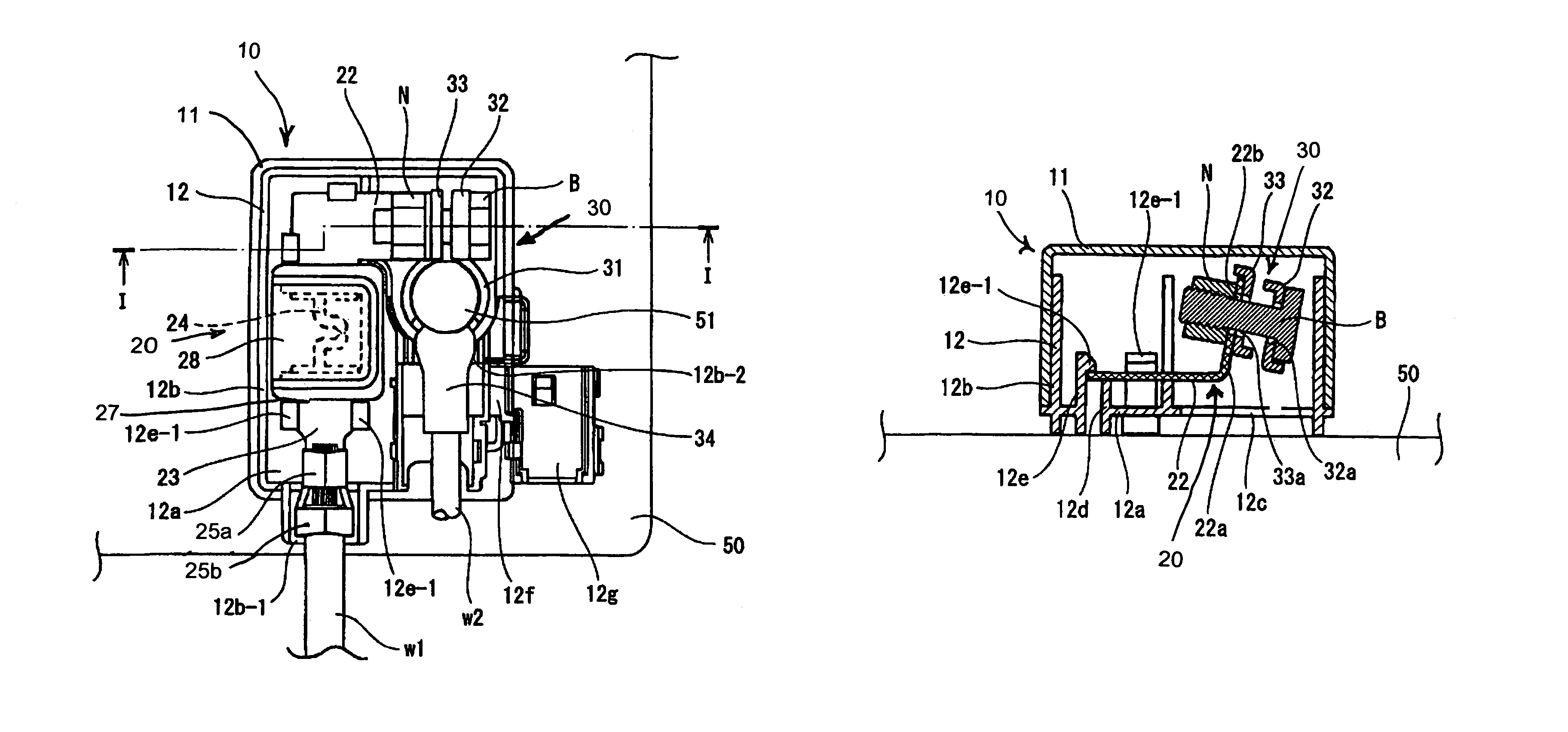
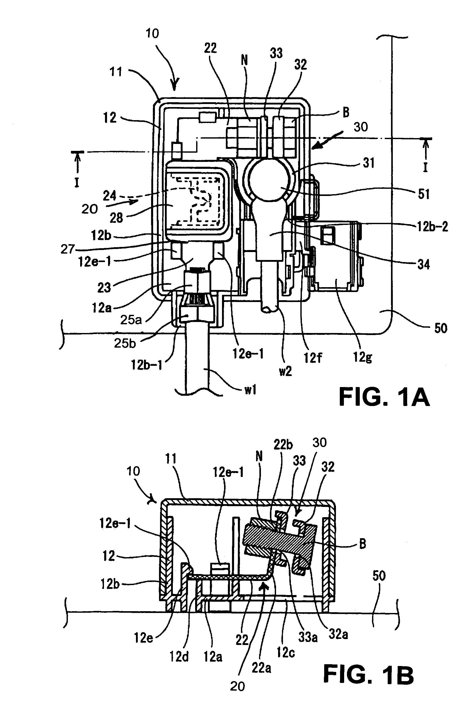
[0035]FIGS. 1 to 3 show a first embodiment of a battery fuse unit in accordance with various exemplary embodiments of the invention. A battery fuse unit 10 comprises a casing including an upper casing member 11 and a lower casing member 12, a fusible link 20 contained in the casing and connected to an end of an output side electrical cable w1 and a battery terminal 30 contained in the casing and connected to an end of an input side electrical cable w2. The battery fuse unit 10 is secured to an upper surface of a battery box 50 to be mounted on a motor vehicle.

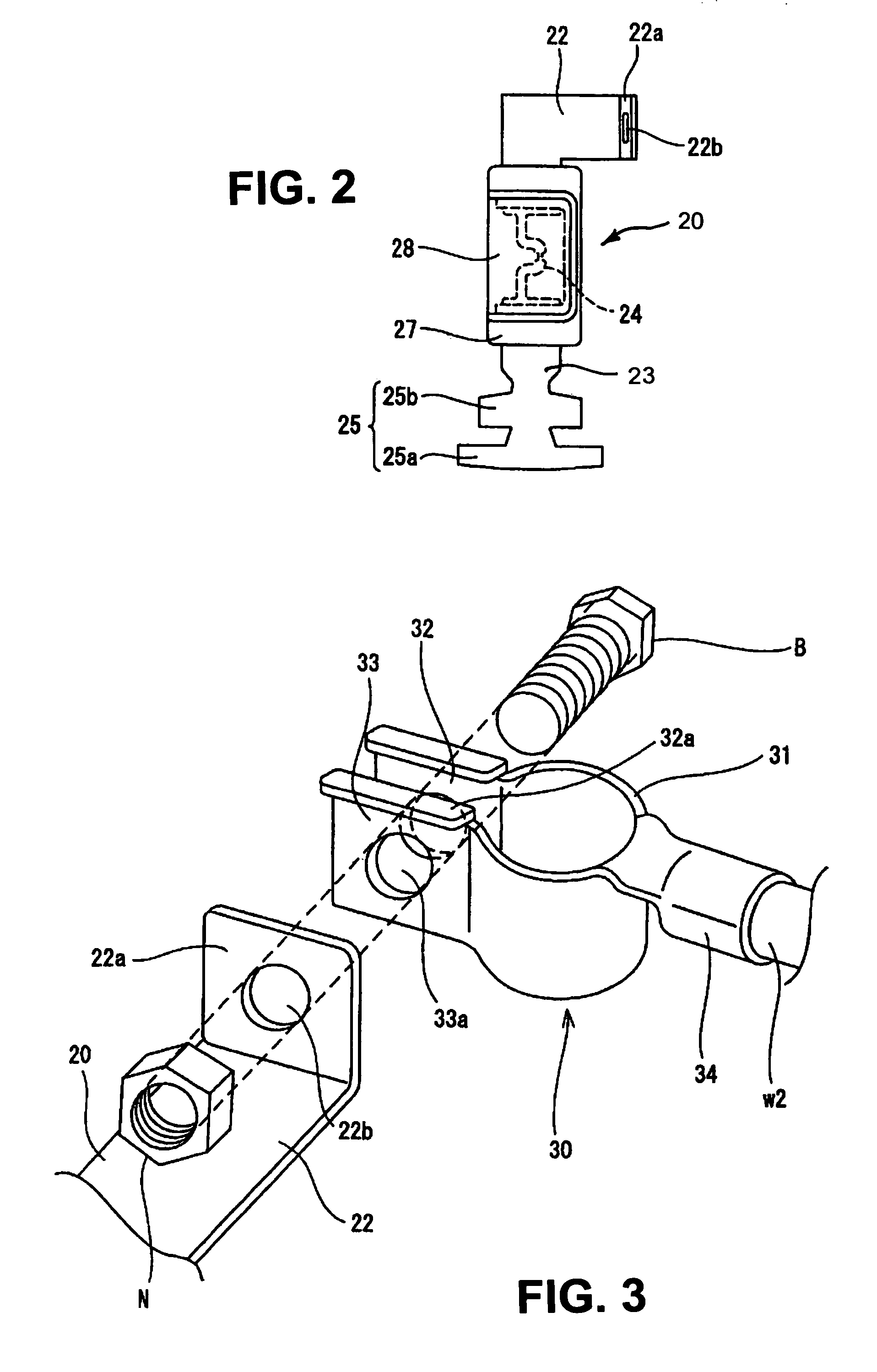
[0036]Punching out an electrically conductive metallic plate forms the fusible link 20 to be contained in the battery fuse unit 10. As shown in FIG. 2, the fusible link 20 includes an input side connecting-section 22, an output side connecting-section 23 extending i...


PUM

PropertyMeasurementUnit
electrically conductiveaaaaaaaaaa
widthaaaaaaaaaa
anglesaaaaaaaaaa

Abstract

A fusible link adapted to be connected to a battery terminal and a compact and thin battery fuse unit that contains the fusible link and battery terminal. The link, formed by punching out an electrically conductive metallic plate, includes an input side connecting-section, an output side connecting-section, a fusible section having a narrow width and provided between the input and output side connecting-sections, and a resin section enclosing the fusible section. Coupling portions between the fusible section and the input and output side connecting-sections are molded in the resin section. The input and output side connecting-sections are arranged on the angled positions with respect to the fusible section. The fusible link and a battery terminal connected to the input side connecting-section of the fusible link are contained in a casing so that arc portions of the battery terminal are exposed from the casing. The arc portions engage a battery post.

Description

CROSS-REFERENCE: TO RELATED APPLICATION[0001]The invention claims priority to Japanese Patent Application No. JP 2003-403456 filed on Dec. 2, 2003. The disclosure of the prior application is incorporated herein by reference in its entirety.BACKGROUND OF THE INVENTION[0002]1. Field of Invention[0003]This invention relates to a fusible link and a battery fuse unit containing the fusible link and more particularly relates to a fusible link adapted to be connected to a battery terminal to be engaged with a battery post and relates to a battery fuse unit that contains the fusible link and the battery terminal in a casing and is adapted to be mounted on a top part of a battery box.[0004]2. Description of Related Art[0005]Heretofore, an output side electrical cable is connected through a battery fuse to a battery terminal to be connected to a battery post. The battery fuse utilizes a fusible link in which a U-shaped terminal member includes an input terminal section, an output terminal sec...

Claims


Application Information

Patent Timeline
Patent Type & Authority Patents(United States)
IPC IPC(8): H01H85/08H01H85/20H01H85/044H01H85/175H01H85/10H01H85/157H01M2/30H01M2/34
CPCH01H85/044H01H2085/025H01H2001/5877
Inventor TAGA, SHUNJINAKAMURA, MASAYOSHI
Owner SUMITOMO WIRING SYST LTD
Why Eureka
Try Eureka