
Architecture, programming model and API'S

a programming model and architecture technology, applied in the field of radio frequency identification, can solve the problems of complex discovery, configuration, setup, communication, security, and/or compatibility within the rfid system and with other rfid systems, and achieve the effect of facilitating the creation and execution of an rfid process

Active Publication Date: 2007-11-13
MICROSOFT TECH LICENSING LLC
View PDF13 Cites 54 Cited by
  • Summary
  • Abstract
  • Description
  • Claims
  • Application Information

AI Technical Summary

Benefits of technology

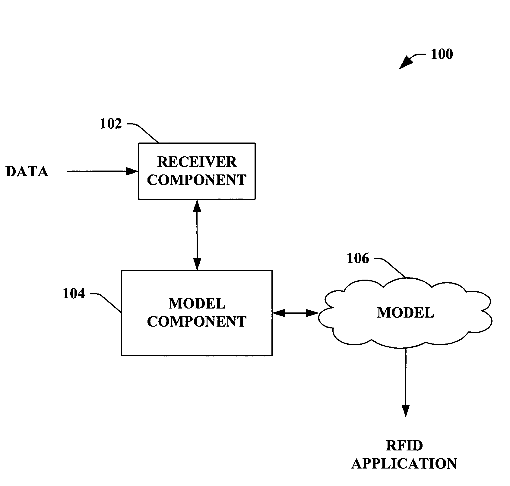
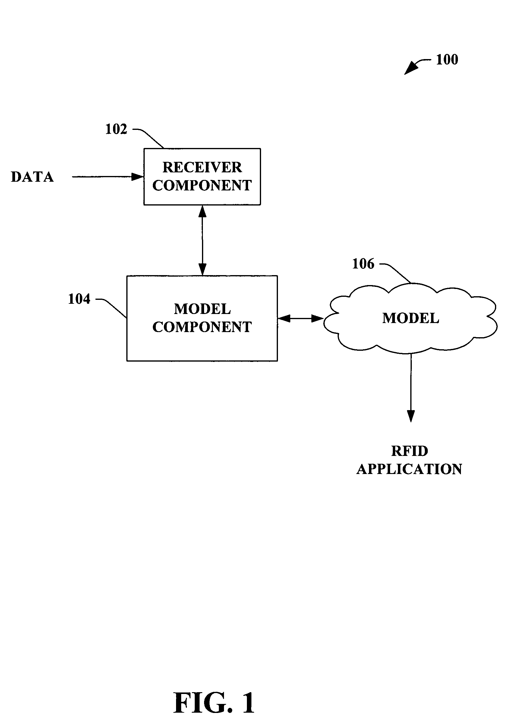
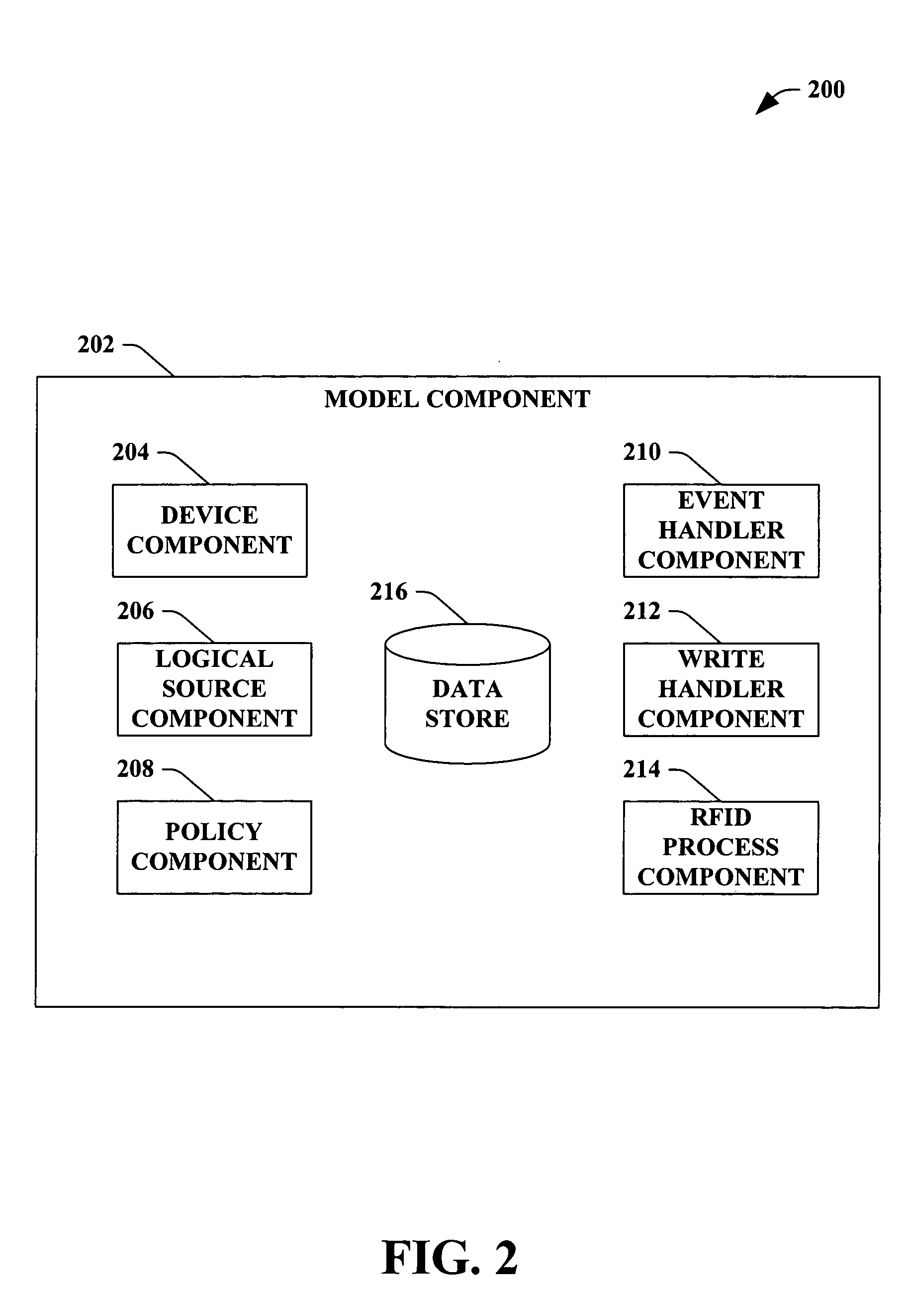
[0010]In accordance with one aspect of the subject invention, the model component can utilize a framework (which can be, but is not limited to, an entity (e.g., a device, a logical source, a filter policy, an alert policy, an event handler, a tracker, a write handler, an RFID process object, a store, etc.), a framework class, a hierarchical framework of at least one class, an interface, an exception, a component architecture, a schema, an object model, an application programming interface (API), . . . ) that facilitates creating and executing an RFID process. The logical source can represent a stream of reads from a physical device on a server that brings an entity together and can represent processing tag data within the RFID process. It is to be appreciated that the model component can encompass at least one of the following device management, provider management, store management, health monitoring, process design, process deployment, and runtime.

Problems solved by technology

Monitoring inventory and associated sales can be a complex task, wherein product activity is comparable to a black box since inner workings are unknown; yet monitoring products is a crucial element in inventory / product efficiency.
Yet, range is limited in RFID based upon radio frequency, RFID tag size, and associated power source.
. . ), which can complicate discovery, configuration, setup, communication, maintenance, security, and / or compatibility within the RFID system and with other RFID systems.

Method used


Image

  • Architecture, programming model and API'S
  • Architecture, programming model and API'S
  • Architecture, programming model and API'S

Examples


Embodiment Construction

[0030]As utilized in this application, terms “component,”“system,”“framework,”“object model,”“model,” and the like are intended to refer to a computer-related entity, either hardware, software (e.g., in execution), and / or firmware. For example, a component can be a process running on a processor, a processor, an object, an executable, a program, and / or a computer. By way of illustration, both an application running on a server and the server can be a component. One or more components can reside within a process and a component can be localized on one computer and / or distributed between two or more computers.

[0031]The subject invention is described with reference to the drawings, wherein like reference numerals are used to refer to like elements throughout. In the following description, for purposes of explanation, numerous specific details are set forth in order to provide a thorough understanding of the subject invention. It may be evident, however, that the subject invention may b...


PUM


Abstract

The subject invention provides a system and / or a method that facilitates employing a model based at least upon a framework, wherein the model can be utilized to build an RFID application. A receiver component can receive data, wherein a model component can create a model based at least in part upon the received data that facilitates creating and / or executing the RFID application. The framework can be, but is not limited to, an entity, a framework class, a hierarchical framework of at least one class, an interface, an exception, a component architecture, a schema, an object model, and / or an API (Application Programming Interface). The model can be utilized to create, deploy, manage, and / or execute the RFID application to provide a generic operation and / or a business specific scenario.

Description

CROSS-REFERENCE TO RELATED APPLICATION(S)[0001]This application claims the benefit of U.S. Provisional Patent Application Ser. No. 60 / 606,281 filed on Sep. 1, 2004, entitled “SYSTEM AND METHODS THAT FACILITATE RFID SERVER PROGRAMMING MODEL AND API'S,” and U.S. Provisional Patent Application Ser. No. 60 / 606,577 filed on Sep. 2, 2004, entitled “FACILITATE RFID SERVER PROGRAMMING MODEL AND API's.” This application is also related to co-pending U.S. patent application Ser. Nos. 11 / 025,702, 11 / 061,356, and 11 / 061,337, filed on Dec. 29, 2004, Feb. 18, 2005, and Feb. 18, 2005, respectively. The entireties of these applications are incorporated herein by reference.TECHNICAL FIELD[0002]The subject invention generally relates to radio frequency identification (RFID), and more particularly to a system and / or a method that generates a framework to create and / or execute an RFID application.BACKGROUND OF THE INVENTION[0003]Many retail, manufacture, and distribution establishments are applying dif...

Claims


Application Information

Patent Timeline
Patent Type & Authority Patents(United States)
IPC IPC(8): G08B13/14
CPCG06Q30/06G06F8/24G06F15/16G06F9/00G06K19/00
Inventor KUMAR, ANUSHGOTETI, JANAKI RAMAHMED, MOHAMED FAKRUDEEN ALIAGARWAL, ABHISHEKSRIRAM, BALASUBRAMANIANVENKATESH, RAMACHANDRAN
Owner MICROSOFT TECH LICENSING LLC
Learn More