Colorant, particles for display device, image display medium and image forming apparatus

a technology of display devices and particles, applied in the field of colorants, can solve the problems of low contrast, conductive color toner which is not conductive, and low degree of contrast achieved

Active Publication Date: 2007-11-13
E INK CORPORATION
View PDF7 Cites 9 Cited by
  • Summary
  • Abstract
  • Description
  • Claims
  • Application Information

AI Technical Summary

Problems solved by technology

Although such display techniques are superb in image memorizing properties, problems have arisen insofar that it has not been possible to secure a white display like paper on a display screen only a low degree of contrast has been achieved.
In the above technologies, however, there is the problem that the conductive color toner which is not in contact with the charge transfer layer disposed on the inside surface of the electrode of the non-display substrate and the conductive color toner isolated from other conductive color toners are present.
And these conductive color toners are not transferred by an electric field but exist at random inside of the substrate because no charge is injected, resulting in low contrast.
However, these color organic pigments have the problem that they are unstable to light so that their colors are faded by light.
Also, these color organic pigments have the drawbacks that a desired tinting strength is not obtained if the amount of the pigment to be added is not substantially increased with a reduction in the diameter of the particles for display device.
The inorganic pigments, on the other hand, have the drawbacks that these pigments have small tinting strength and therefore, a desired tinting strength is not obtained if the amount of the pigment to be added to the particles for display device is not substantially increased.
However, it is technically difficult to develop such a pigment.

Method used


Image

  • Colorant, particles for display device, image display medium and image forming apparatus
  • Colorant, particles for display device, image display medium and image forming apparatus
  • Colorant, particles for display device, image display medium and image forming apparatus

Examples


first embodiment

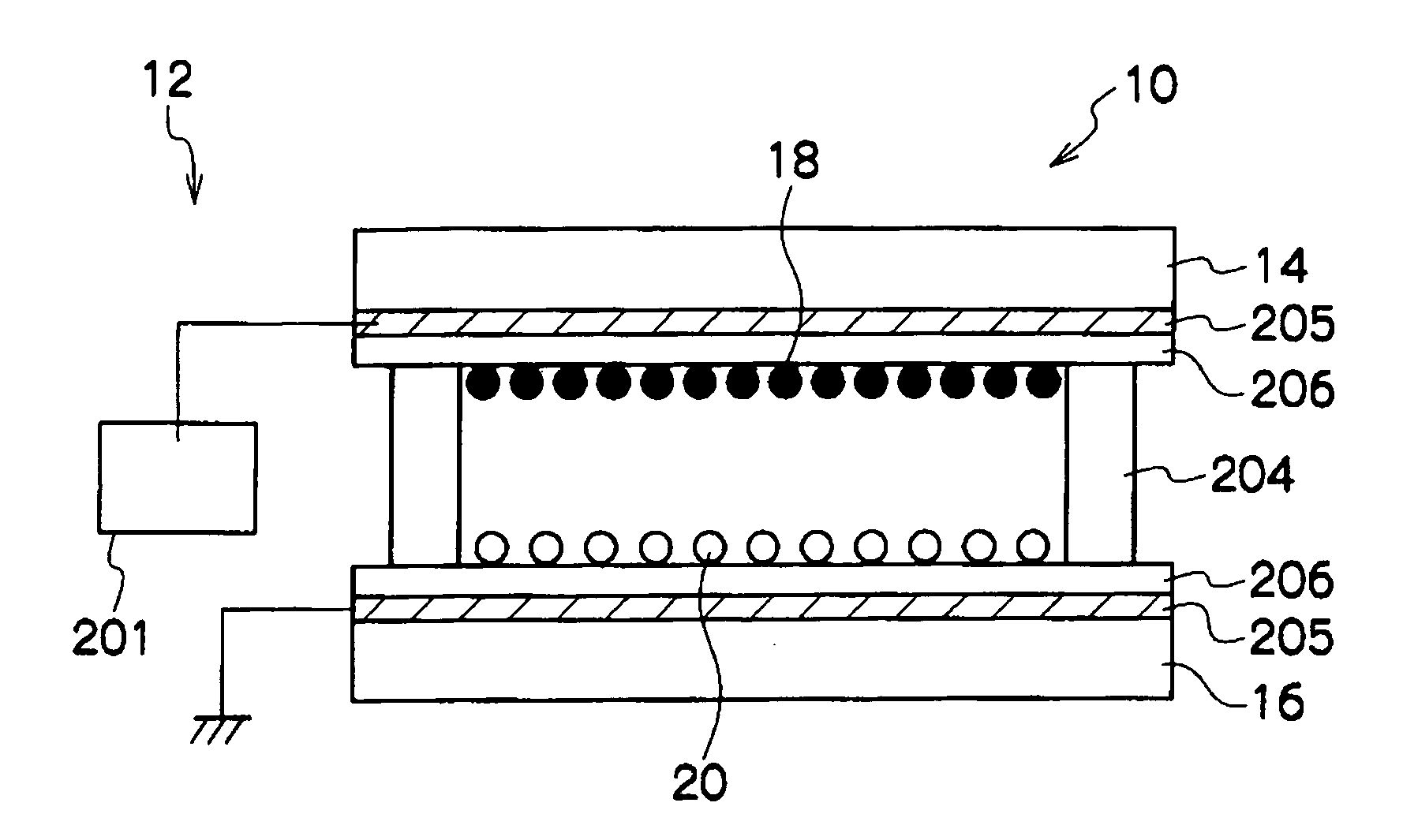
[0100]FIG. 1 is a simplified structural view of an example (first embodiment) of the image forming apparatus of the invention.

[0101]The image forming apparatus 12 according to the first embodiment is provided with a voltage applying means 201 as shown in FIG. 1. An image display medium 10 is provided with a display substrate 14 on the side on which an image is displayed, a non-display substrate 16 facing the display substrate 14 and a spacer 204 disposed so as to seal the outside peripheries of these two substrates. Red particles 18 and white particles 20 are sealed as display particles in the gap partitioned by the display substrate 14, the non-display substrate 16 and the spacer 204. A transparent electrode 205 is disposed on the side facing each of the display substrate 14 and the non-display substrate 16. The transparent electrode 205 disposed on the side facing the non-display substrate 16 is grounded and the transparent electrode 205 disposed on the side facing the display sub...

second embodiment

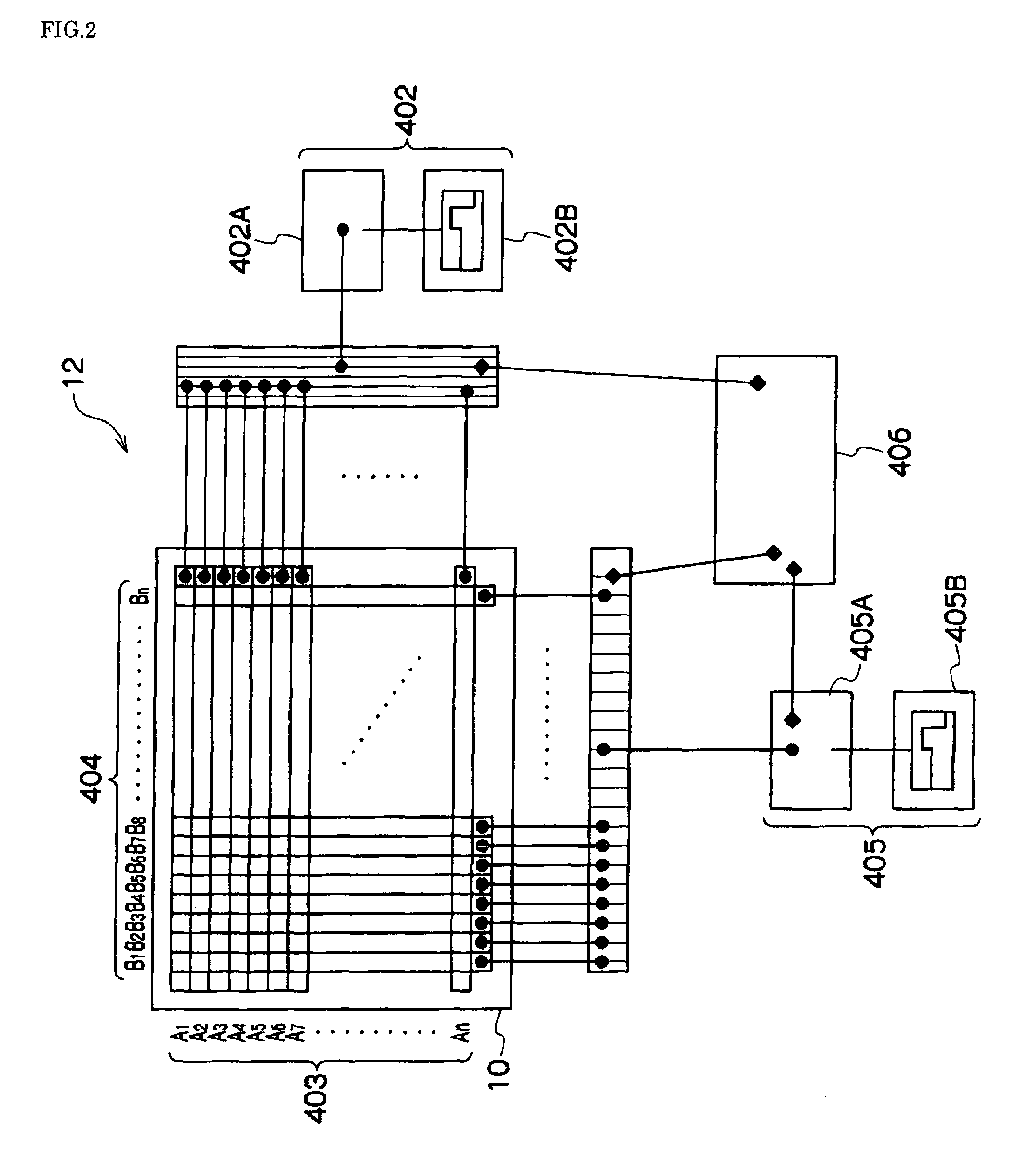
[0107]A second embodiment of the invention will be described in detail as follows, with reference to the drawings.

[0108]FIG. 2 is a simplified structural view of another example (second embodiment) of the image forming apparatus of the invention, and shows the image forming apparatus 12 for forming images on the image display medium 10 using a simple matrix.

[0109]In the plane direction of the image display medium 10 into which plural (unillustrated) types of display particles having different charging properties have been sealed, electrodes 403An and 404Bn (n is a positive number) for controlling the voltages in the vertical and lateral directions are arranged to form a simple matrix structure. The electrodes 403An are connected with a power source 405A of the electric field generator 405 which has a waveform generator 405B and the power source 405A. The electrodes 404Bn are connected with a power source 402A of an electric field generator 402 having a waveform generator 402B and th...

third embodiment

[0114]The third embodiment of the invention will be hereinafter explained in detail with reference to the drawings. FIG. 6 is a schematic structural view showing another example (third embodiment) of the image forming apparatus, showing, specifically, an image forming apparatus using a printing electrode.

[0115]An image forming apparatus 12 shown in FIG. 6 is constituted of a printing electrode 11 and a counter electrode 26 which is disposed so as to face the printing electrode 11 and connected to the earth.

[0116]The image display medium 10 is designed to be movable in the direction of the arrow B through the space between the printing electrode 11 and the counter electrode 26. The image display medium 10 is constituted of a pair of substrates (display substrate 14 and non-display substrate 16) and the particles 18 and 20 sealed between these substrates. When the image display medium 10 is conveyed in the direction of the arrow B, it is conveyed such that the non-display substrate 16...


PUM

PropertyMeasurementUnit
particles diameteraaaaaaaaaa
volume average particles diameteraaaaaaaaaa

Abstract

Disclosed are a colorant comprising a particulate base material and particles having the color strength due to the surface plasmon resonance, the particles being supported on or contained in the particulate base material, particles for display device using the colorant, an image display medium using the particles for display device and an image forming apparatus using the image display medium.

Description

[0001]This application claims priority under 35 USC 119 from Japanese Patent Application No. 2005-172779, the disclosure of which is incorporated by reference herein.BACKGROUND OF THE INVENTION[0002]1. Field of the Invention[0003]The present invention relates to a colorant, particles for display device comprising the colorant, an image display medium and an image forming apparatus.[0004]2. Description of the Related Art[0005]Traditionally, various display techniques have been proposed as an image display medium repeatedly rewritable thereon, such as a Twisting Ball Display (bicolor saturationl particles rotational display) medium, an electrophoresis medium, a magnetophoresis medium, a thermal rewritable medium and a liquid crystal medium having a memorizing property. Although such display techniques are superb in image memorizing properties, problems have arisen insofar that it has not been possible to secure a white display like paper on a display screen only a low degree of contra...

Claims


Application Information

Patent Timeline
Patent Type & Authority Patents(United States)
IPC IPC(8): G02B26/00G09G3/34G02F1/167
CPCG02F1/167G02F2001/1678G02F2203/10B82Y30/00C09C1/62C09C1/0084C09C1/0081C01P2004/62C01P2006/40C01P2006/16C01P2004/64C01P2004/61B82Y20/00
Inventor YAMAMOTO, YASUO
Owner E INK CORPORATION
Why Eureka
Try Eureka