Load carrier arrangement for a vehicle bed comprising an internal bed rail system

a technology of bed structure and load carrier, which is applied in the direction of vehicle to carry long loads, supplementary fittings, building scaffolds, etc., can solve the problems of loss of structural rigidity, inability to secure the load carrier upon some types of new vehicles, and current load carrier and clamping assembly not configured for being secured, etc., to achieve the effect of substantially preventing the twisting with respect to the vehicle and being easy to adjus

Active Publication Date: 2007-11-20
THULE SWEDEN AB
View PDF14 Cites 44 Cited by
  • Summary
  • Abstract
  • Description
  • Claims
  • Application Information

AI Technical Summary

Benefits of technology

[0008]The present invention also derives a benefit from the more flexible construction of the top of the truck's bed wall (top rail), as well in the newly-employed rail assemblies. When the mounting assemblies of the present invention are tightened into a transporting configuration, a substantially rigid component is established. This rigid component which spans between the top rail and rail assembly provides a solid mounting for the carrier components supported thereupon. Because the mounting assembly is anchored at both top and bottom locations, twist with respect to the vehicle is substantially prevented. Moreover, the flexibility of the truck components causes them to bias outwardly against the tightened mounting hardware in the transporting configuration thereby beneficially acting as a takeout mechanism for looseness that may result in the interconnection between the carrier's mounting hardware and the vehicle during use.
[0009]In at least one exemplary embodiment, the present invention provides a load carrier that is mountable above a bed structure of a vehicle having an upper surface and an internal bed rail system. The load carrier broadly includes an upright base support member, an internal rail clamping assembly, and a clamp adjustment assembly. The upright base support member is connected to the rail clamping assembly and forms a first clamp surface for asserting a clamping force upon the upper surface of the vehicle side wall, or top rail. The rail clamping assembly is releasably securable to a rail of the internal bed rail system and forms a second clamp surface configured to assert a clamping force upon the rail. The rail clamping assembly is also configured for sliding movement with respect to the upright base support member as well as the rail of the internal bed rail system such that the load carrier's position relative to a long axis of the carrying vehicle may be readily adjusted. The clamp adjustment assembly is configured for positionally adjusting the first clamping surface with respect to the second clamping surface between clamped and unclamped positions.

Problems solved by technology

While the above-described XSPORTER carrier and associated clamping assemblies remain popular and successful, they are, however, occasionally incapable of securing load carriers upon some types of new vehicles; i.e., pickup trucks having new types of top rail structure and / or internal bed rail systems; examples include the 2006 TOYOTA TACOMA, 2006 HONDA RIDGELINE, AND 2006 NISSAN TITAN AND FRONTIER pickup trucks.
In these examples the new top rail structures are not generally J-shaped and / or do not generally allow ready access to the upper and lower surfaces of the top rail.
Similarly, current load carriers and clamping assemblies therefor are not configured for being secured to the rails of the internal bed rail systems of these newer vehicles.
This loss in structural rigidity further contributes to the difficulties experienced in mounting load carriers of the present type upon pickup trucks where these carriers have traditionally relied heavily upon the fortitude of the top rail of the truck bed.
This presents a problem for load carrier manufacturers in that the use of universal mounting hardware is no longer possible and a wide variety of differently configured mounting hardware must be provided in order to accommodate owners of different vehicles.
This means that this cost-saving move of the truck manufacturers has resulted in a cost increase to the load carrier manufacturers.

Method used


Image

  • Load carrier arrangement for a vehicle bed comprising an internal bed rail system
  • Load carrier arrangement for a vehicle bed comprising an internal bed rail system
  • Load carrier arrangement for a vehicle bed comprising an internal bed rail system

Examples


Embodiment Construction

[0027]The present invention will now be described and disclosed in greater detail. It is to be understood, however, that the disclosed embodiments are merely exemplary of the invention and that the invention may be embodied in various and alternative forms. Therefore, specific structural and / or functional details disclosed herein are not to be interpreted as limiting the scope of the claims, but are merely provided as an example to teach one having ordinary skill in the art to make and use the invention.

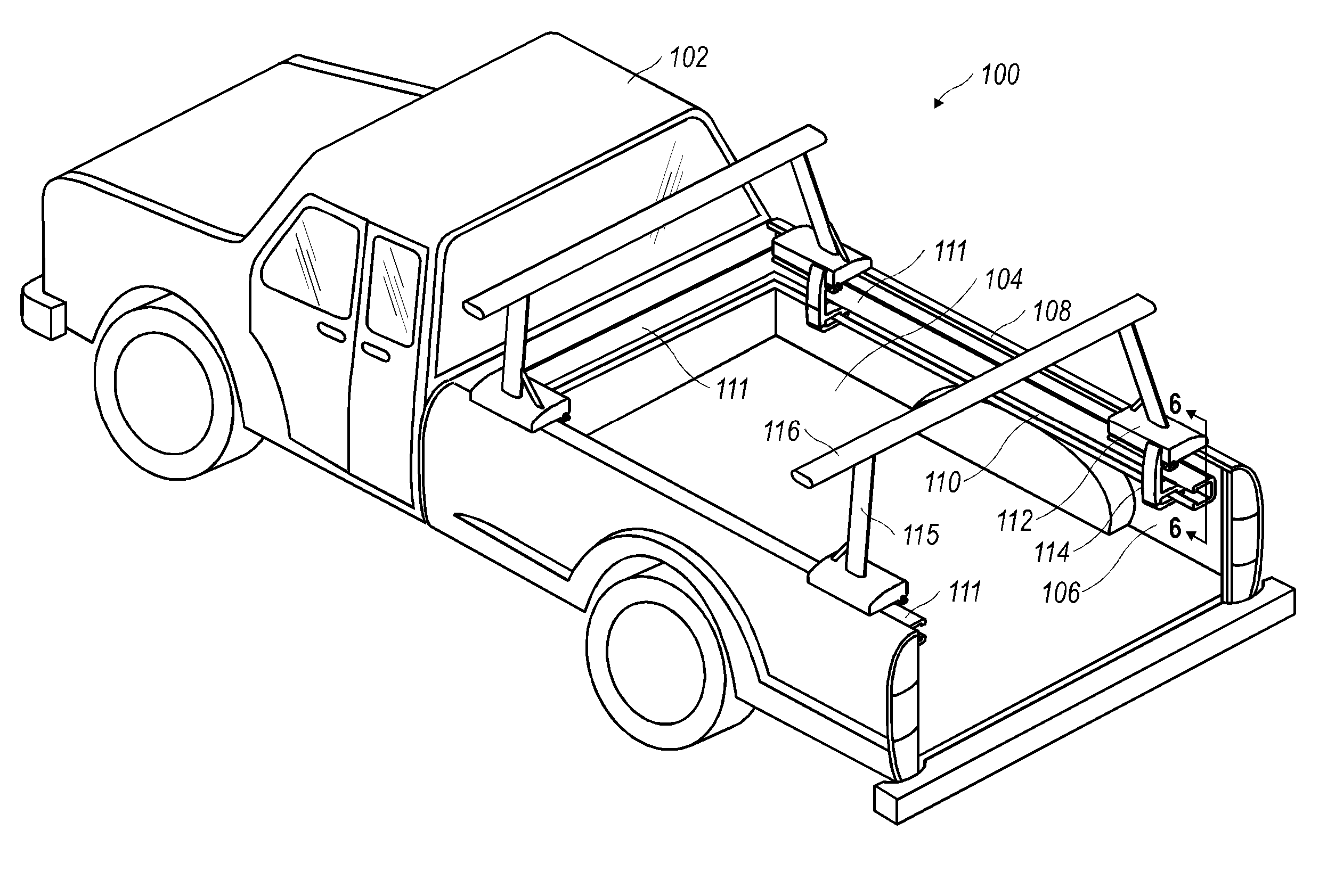
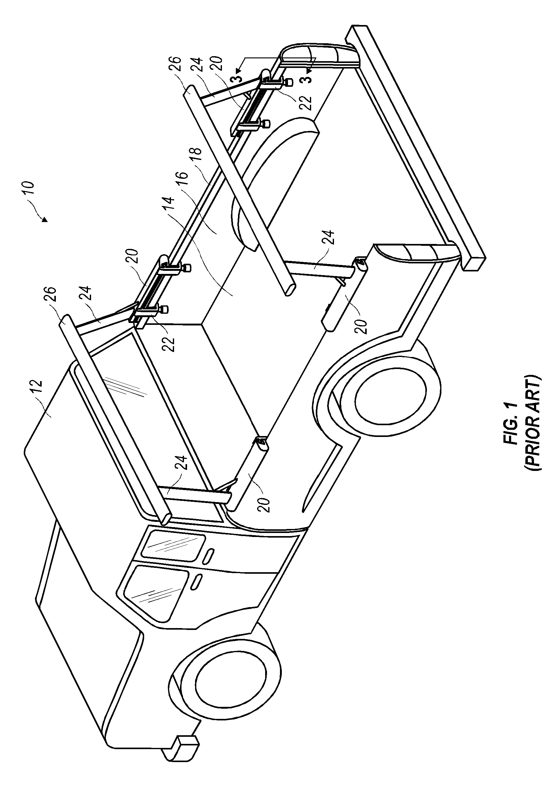
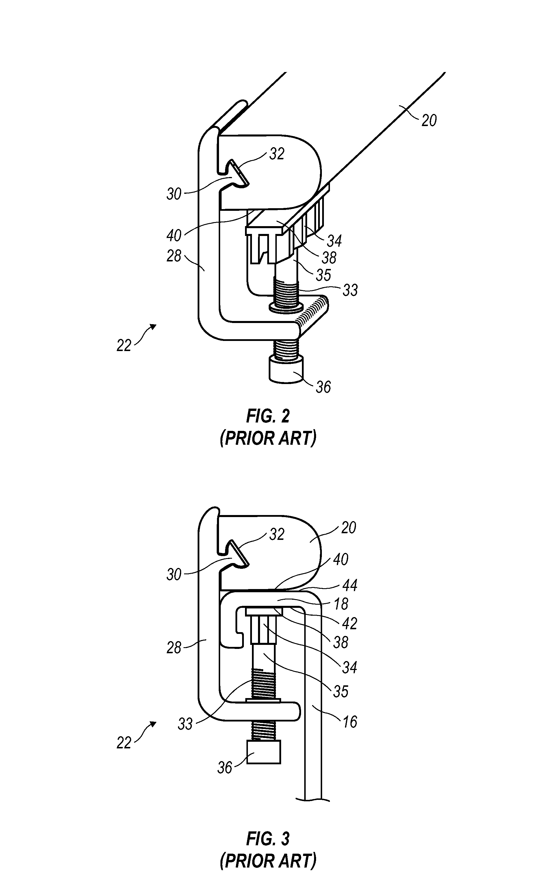
[0028]At the outset, a description of the structure of a known vehicle bed structure and load carrier therefor is provided for further illustrating the present invention. Referring to FIGS. 1-3, a load carrier 10 of known design is illustrated as being fixed to vehicle 12 having a bed structure 14. In the illustrated embodiment, vehicle 12 is a common pickup-type truck wherein bed structure 14 broadly comprises side walls 16 and top rails 18 having upper surfaces 44 (see FIG. 3). Top...


PUM


Abstract

Load carrier mountable above a bed structure of a vehicle having an upper surface and an internal bed rail system is disclosed. The load carrier broadly includes an upright base support member, an internal rail clamping assembly, and a clamp adjustment assembly. The upright base support member rests upon the upper surface of the side wall of the bed structure and connects with the internal rail clamping assembly. The upright base support member has a first clamp surface for asserting a clamping force upon the upper surface of the side wall of the bed structure. The rail clamping assembly is releasably securable to the internal bed rail system and includes a second clamp surface for asserting a clamping force upon the internal bed rail system. The clamp adjustment assembly positionally adjusts the first clamping surface with respect to the second clamping surface between clamped and unclamped positions.

Description

FIELD OF THE INVENTION[0001]The present invention relates generally to load carriers for vehicles having bed structures, and more specifically, to vehicles having bed structures comprising internal bed rail systems.BACKGROUND OF THE INVENTION[0002]Load carriers, and particularly sports equipment carriers, for vehicles having bed structures are known devices for transporting cargo above the bed structure of a vehicle. Common uses of such load carriers can include the transport of generally elongate objects, such as ladders, piping, lumber, construction materials, etc. Likewise, sport related uses of such load carriers can include the transport of canoes, kayaks, paddles and similar equipment. An example of a particularly commercially successful load carrier for a vehicle having a bed structure is Thule's XSPORTER carrier.[0003]As illustrated in FIGS. 1-3 of the present application, the XSPORTER carrier broadly includes a plurality of upright base support members each configured for s...

Claims


Application Information

Patent Timeline
Patent Type & Authority Patents(United States)
IPC IPC(8): B60R9/00
CPCB60P3/40B60R9/00B60R11/00B60R2011/0061B60R2011/004B60R2011/0059B60R2011/0036
Inventor NIEDZIELA, TEDFORTUNE, WILLIAMHARRIS, KEVIN
Owner THULE SWEDEN AB
Why Eureka
Try Eureka