
Method and device for determining refractive components and visual function of the eye for vision correction

a technology of refractive components and visual function, which is applied in the field of ophthalmologic methods and medical ophthalmologic equipment, can solve the problems of not being able to take measurements on dilated pupils without using medicines, and existing devices did not incorporate means for providing

Inactive Publication Date: 2007-12-04
TRACEY TECH
View PDF36 Cites 70 Cited by
  • Summary
  • Abstract
  • Description
  • Claims
  • Application Information

AI Technical Summary

Problems solved by technology

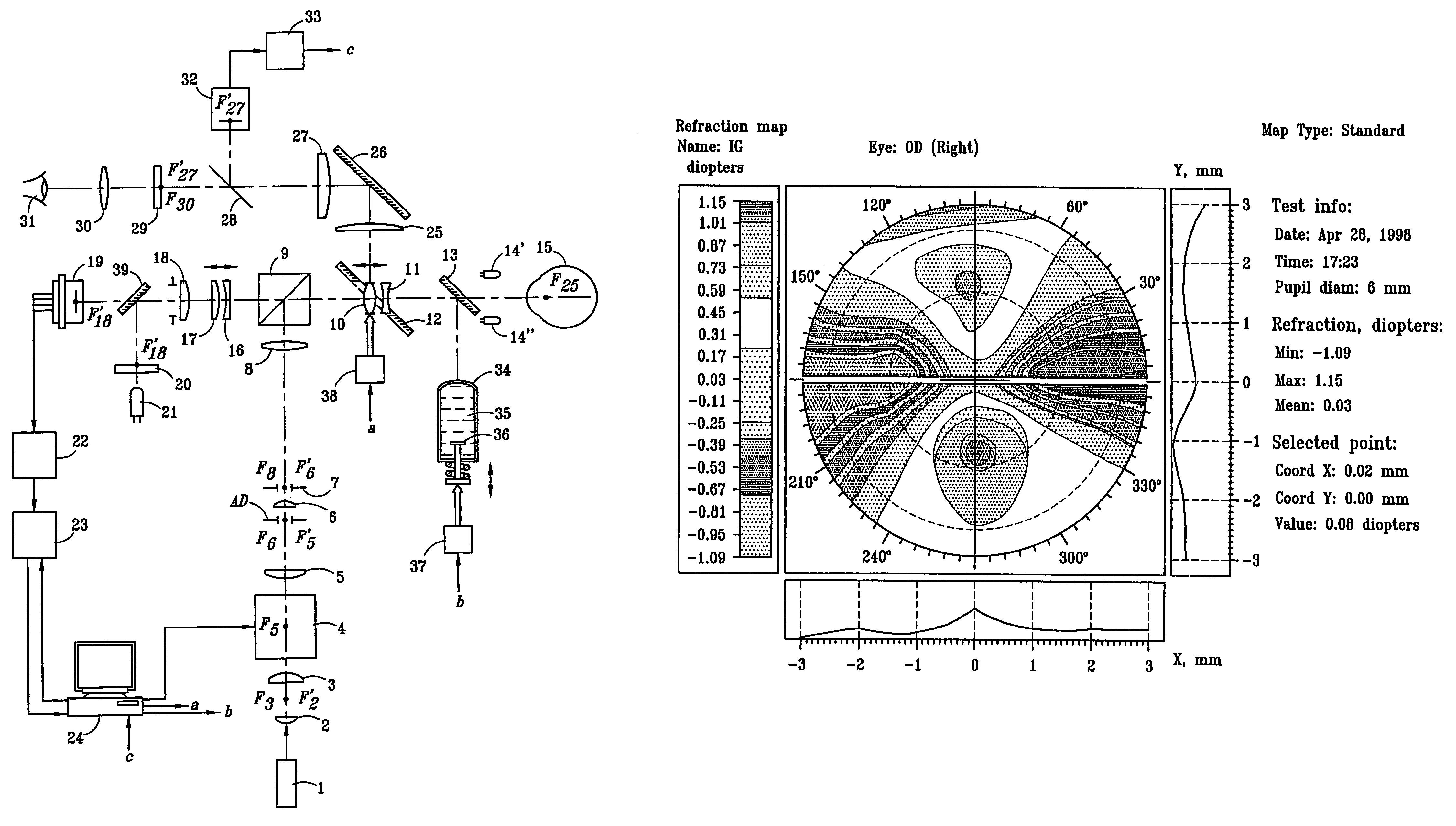
Previously, existing devices did not incorporate means for providing an accurate reproducible “linkage” of the patient's eye to the spatial co-ordinates of the measuring device; they did not incorporate a means for adjusting the accommodation of the patient's eye that is necessary for studying the dependence of aberrations on the accommodation characteristics; they were not capable of taking measurements on a dilated pupil without using medicines.

Method used


Image

  • Method and device for determining refractive components and visual function of the eye for vision correction
  • Method and device for determining refractive components and visual function of the eye for vision correction
  • Method and device for determining refractive components and visual function of the eye for vision correction

Examples


Embodiment Construction

[0028]While the making and using of various embodiments and methods of the present invention are discussed in detail below, it should be appreciated that the present invention provides many applicable inventive concepts which may be employed in a variety of specific contexts. The specific embodiments discussed herein are merely illustrative of specific ways to make and use the invention and do not delimit the scope of the invention.

[0029]With the advent of modern methods for correcting total refractive errors of the eye and / or errors associated with the intraocular lens alone, it has become increasingly important to understand the physics of vision. The goal of “perfect vision” is an elusive one today. More often than not, perfect vision is obtained by chance and not calculation. New diagnostic instrumentation such as corneal topography have enabled today's ophthalmic surgeons to more greatly appreciate the detail and variability of the cornea's shape and hence its refractive power....


PUM


Abstract

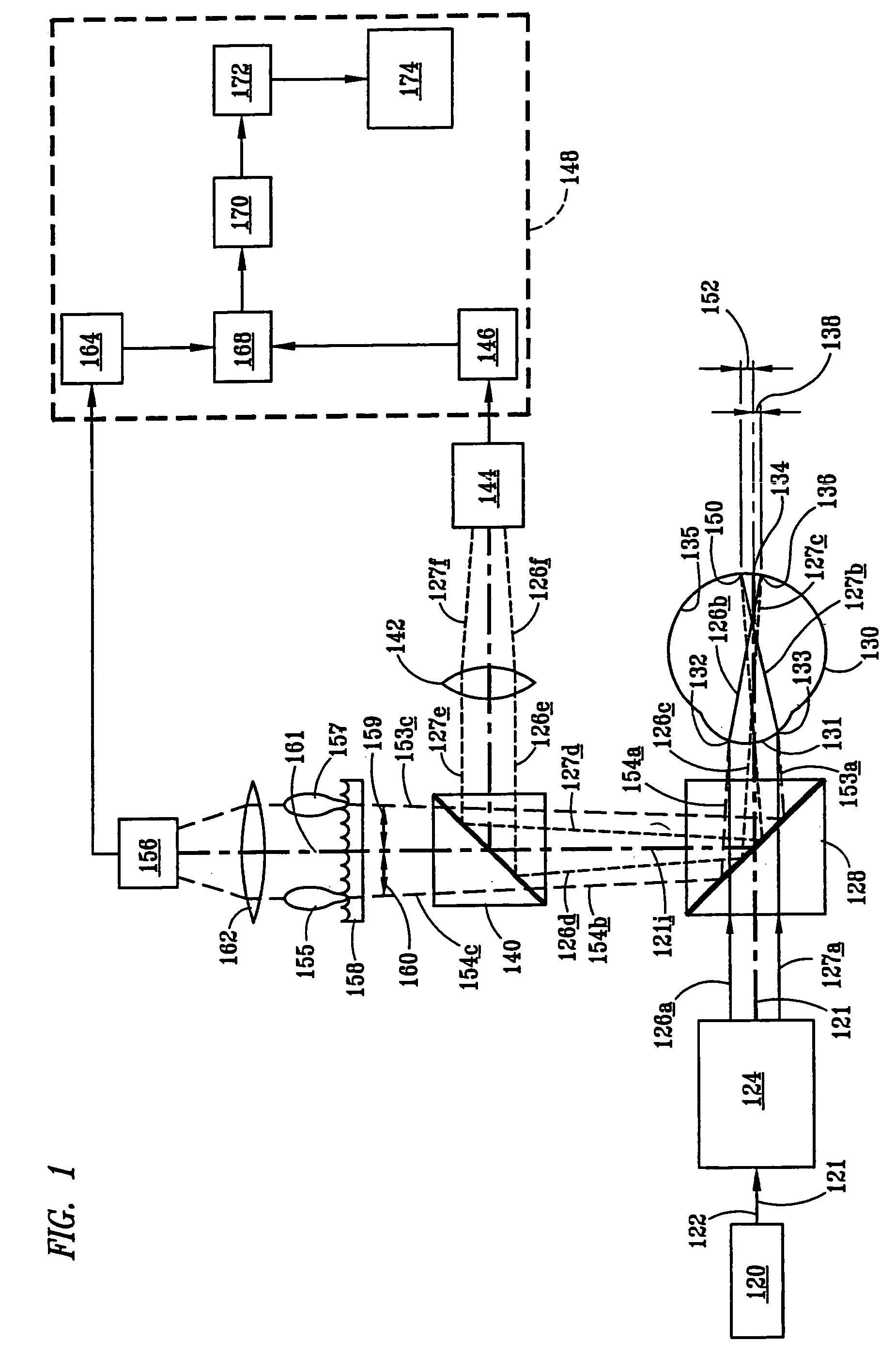
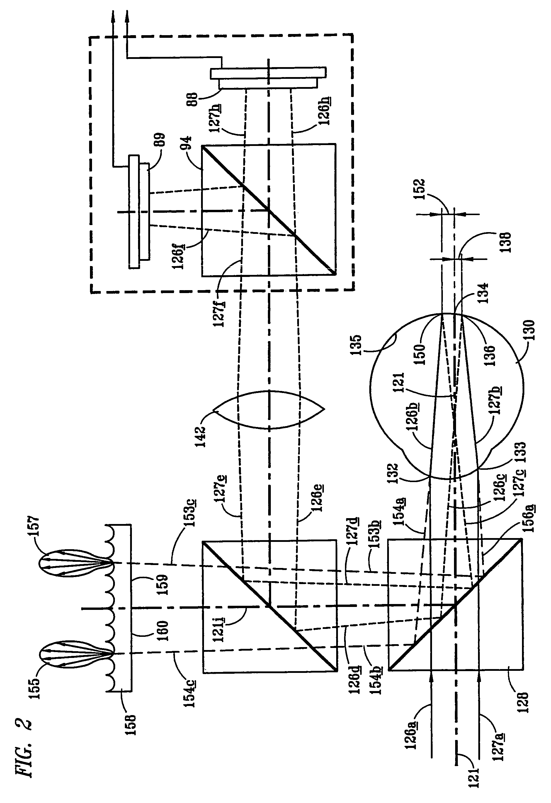
A method and an instrument is provided for measuring aberration refraction of an eye with a first device for measuring the total aberration refraction of the eye and a second device for measuring the aberration refraction of the cornea of the eye. The component of aberration refraction caused by the lens caused by the lens is calculated using the measured total eye aberration refraction and the measured component of aberration refraction of the cornea mapped over the optical surfaces of the eye. Each component portion of the aberration refraction provides information usable for making appropriate corrective actions at the cornea, at the lens, or both as indicated by the mapped measurements and calculations.

Description

CROSS-REFERENCE TO RELATED PATENTS AND APPLICATIONS[0001]This is a continuation-in-part of U.S. application Ser. No. 10 / 137,720 filed May 1, 2002, now U.S. Pat. No. 6,932,475 which was a continuation-in-part of Ser. No. 09 / 634,487 filed Aug. 8, 2000 (issued as U.S. Pat. No. 6,409,345) which was a continuation-in-part of PCT Application No. PCT / US99 / 23327 filed Oct. 7, 1999, in which the U.S. is a designated country, and claiming priority from Ukrainian Application No. 98105286 filed Oct. 7, 1998, all relied upon for priority and all incorporated by reference herein for all legitimate purposes.[0002]This application is also continuation-in-part of each of the following: PCT / US02 / 12141 filed Apr. 16, 2002, designating the U.S. and claiming priority from U.S. 60 / 284,364 filed Apr. 16, 2001, co-pending with the present application and co-owned at the time of the invention; PCT / US02 / 24075 filed Jul. 29, 2002, claiming priority from U.S. 60 / 308,301 filed Jul. 27, 2001, co-pending with the...

Claims


Application Information

Patent Timeline
Patent Type & Authority Patents(United States)
IPC IPC(8): A61B3/10A61BA61B3/00A61B3/103A61B3/107
CPCA61B3/107A61B3/1015A61B3/0025A61B3/103
Inventor WAKIL, YOUSSEF S.MOLEBNY, VASYLPALLIKARIS, IOANNIS G.MOLEBNY, SERGIYPADRICK, TOM
Owner TRACEY TECH
Learn More