Closed Loop System and Method for Ablating Lenses with Aberrations

a closed loop and aberration technology, applied in the field of aberration-based lenses, can solve the problems of less than ideal corneal sculpting, unnecessary errors in ablation, and less than ideal optical correction

Inactive Publication Date: 2009-05-14
AMO MFG USA INC
View PDF35 Cites 26 Cited by
  • Summary
  • Abstract
  • Description
  • Claims
  • Application Information

AI Technical Summary

Problems solved by technology

For example, deviation from a desired laser beam shape or size, such as the laser beam exhibiting a non-symmetrical shape or an increased or decreased laser beam diameter, may result in tissue ablation at an undesired location on the patient's cornea which in turn leads to less than ideal corneal sculpting results.
The known laser calibration and test methods may result in errors or “noise” which can lead to a less than ideal optical correction.
Furthermore, the known calibration techniques are somewhat indirect, and may lead to unnecessary errors in ablation, as well as a lack of understanding of the physical correction performed.

Method used


Image

  • Closed Loop System and Method for Ablating Lenses with Aberrations
  • Closed Loop System and Method for Ablating Lenses with Aberrations
  • Closed Loop System and Method for Ablating Lenses with Aberrations

Examples


Embodiment Construction

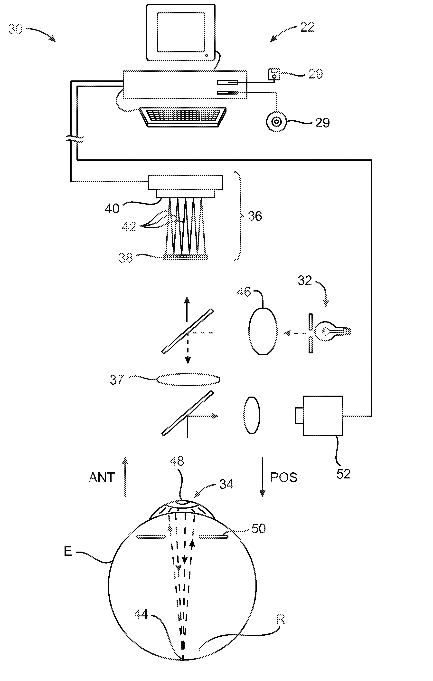
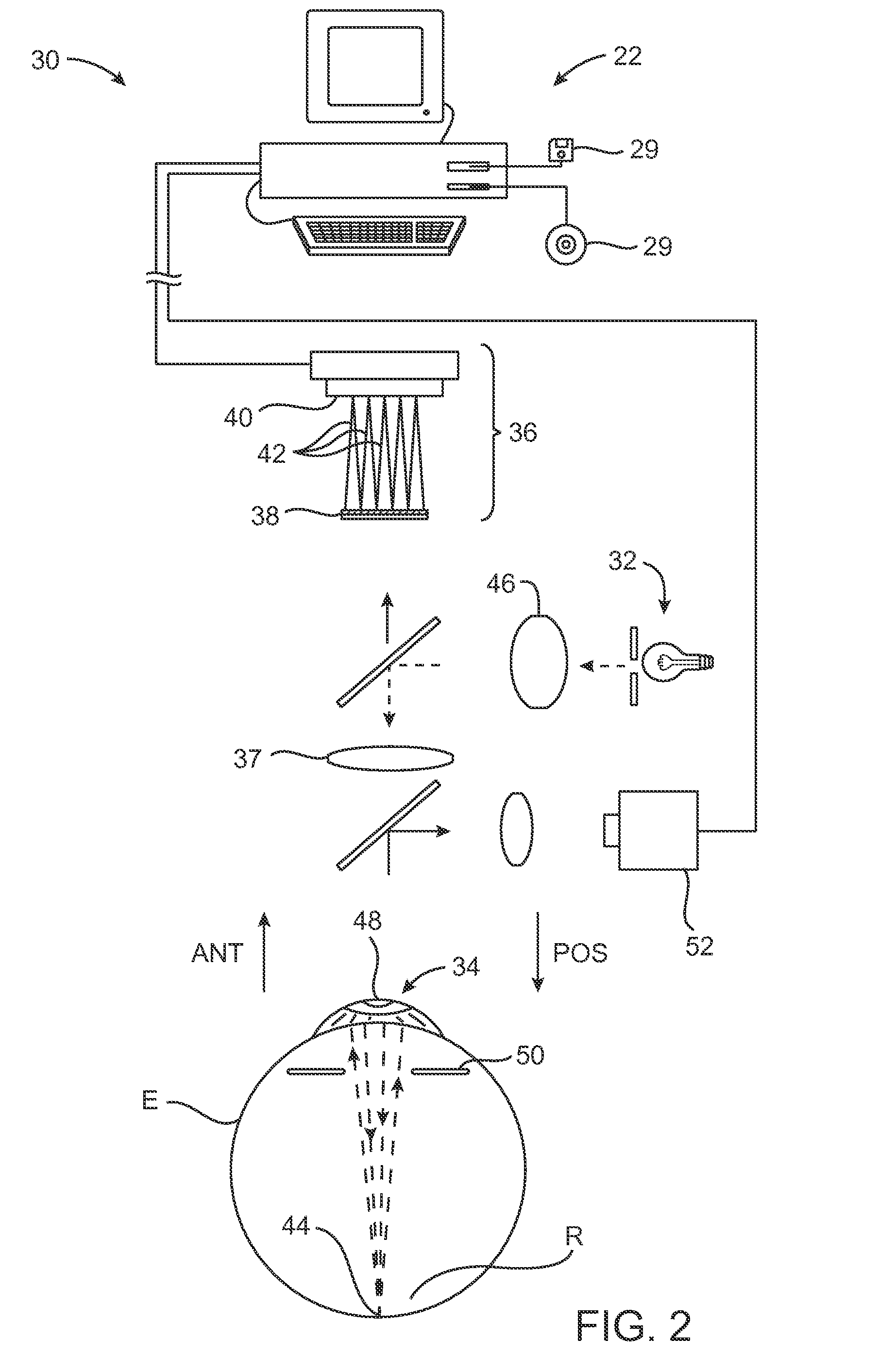
[0033]The present invention is particularly useful for enhancing the accuracy and efficacy of laser eye surgical procedures, such as photorefractive keratectomy (PRK), phototherapeutic keratectomy (PTK), laser in situ keratomileusis (LASIK), and the like. Preferably, the present invention can provide enhanced optical accuracy of refractive procedures by improving the methodology for calibrating, testing and validating a corneal ablation or other refractive treatment program. Hence, while the system and methods of the present invention are described primarily in the context of a laser eye surgery system, it should be understood the techniques of the present invention may be adapted for use in alternative eye treatment procedures and systems such as spectacle lenses, intraocular lenses, contact lenses, corneal ring implants, collagenous corneal tissue thermal remodeling, and the like.

[0034]The techniques of the present invention can be readily adapted for use with existing laser syste...


PUM


Abstract

The present invention comprises a closed loop system and method for assessing a performance of a refractive surgical system that is capable of correcting lower and higher order aberrations of the eye. In one embodiment, the refractor surgical system comprises a corneal re-shaping laser system and a refractor system that is capable of measuring low and higher order aberrations of the eye. A software application is capable of transforming the measurements of the refractor system to a treatment plan to control and guide the corneal re-shaping laser system. The systems and methods of the present invention may include a lens that is created by the corneal reshaping laser system and can be measured by the refractor system.

Description

CROSS-REFERENCES TO RELATED APPLICATIONS[0001]The present application is a continuation of U.S. patent application Ser. No. 10 / 364,886 filed Feb. 11, 2003, which application claims benefit of U.S. Provisional Patent Appln. No. 60 / 356,672 filed Feb. 11, 2002; the full disclosures of which are incorporated herein by reference in their entirety.[0002]The present application is also related to U.S. Provisional Patent Appln No. 60 / 356,658 entitled “Apparatus and Method for Determining Relative Positional and Rotational Offsets between a First and Second Imaging Device,” and Provisional Patent Appln. No. 60 / 356,657 entitled “Method and Device for Calibrating an Optical Wavefront System,” both of which were filed on Feb. 11, 2002; the full disclosures of which are incorporated herein by reference in their entirety.BACKGROUND OF THE INVENTION[0003]The present invention is generally related to design, manufacture, and measurement of lenses with aberrations. The invention provides devices, sy...

Claims


Application Information

Patent Timeline
Patent Type & Authority Applications(United States)
IPC IPC(8): A61F9/008A61B17/00A61F9/007G02C13/00A61F9/01
CPCA61B2017/00725A61F9/00806A61F9/00817A61F2009/0088A61F2009/00855A61F2009/00872A61F2009/00848
Inventor CHERNYAK, DIMITRICAMPBELL, CHARLESPERSOFF, JEFFREY J.
Owner AMO MFG USA INC
Why Eureka
Try Eureka