Subjective Wavefront Refraction Using Continuously Adjustable Wave Plates of Zernike Function

a wave plate and function technology, applied in the field of subjective wavefront refraction using continuously adjustable wave plate of zernike function, can solve the problems of not even being able to find the optimal sphere, cylinder and axis of the patient, and unable to correct the pre-operation errors

Active Publication Date: 2007-11-08
LAI SHUI T
View PDF99 Cites 29 Cited by
  • Summary
  • Abstract
  • Description
  • Claims
  • Application Information

AI Technical Summary

Benefits of technology

[0036] A computer program product may include a processor and a computer program for calculating amplitudes of the ACA plates from relative and/or absolute angular movement and/or for calculating diopter power of the DCA. Readable results may be output. The computer program product may also form an ordered list of decreasing significance of Zernike functions based on RMS amplitude of a patient's measured wavefront errors. The computer program product may also control measurements according to the ordered list. Measurements for Zernike functions having a RMS amplitude less than 0.05 may be omitted. The ordered list may include second order Zernike function, Coma, Trefoil and secondary astigmatism.
[0037] The optical instrument may further include an input device for the patient or for an examination administrator or both. The image source may include a plane wave light source including substantially a point light source as a viewing target. A quality vision marker (QVM) may include one or more display items including one or more lines, one or more circles, one or more points disposed along a pattern of one or more lines or circles, or combinations ther

Problems solved by technology

However, laser surgery is invasive and the tissue healing process following surgery can induce its own set of aberrations, often rendering an attempt to correct the pre-operation errors fruitless.
However, lacking in that disclosure is the basis for a patient to adjust each of the wavefront components.
More importantly, no method is presented regarding how a patient may choose which Zernike function to vary among the dozens of Zernike functions, without which the patient would have to go on a random walk, using by trial and error on all or substantially all of the Zernike functions.
Without a clear step by s

Method used


Image

  • Subjective Wavefront Refraction Using Continuously Adjustable Wave Plates of Zernike Function
  • Subjective Wavefront Refraction Using Continuously Adjustable Wave Plates of Zernike Function
  • Subjective Wavefront Refraction Using Continuously Adjustable Wave Plates of Zernike Function

Examples


Embodiment Construction

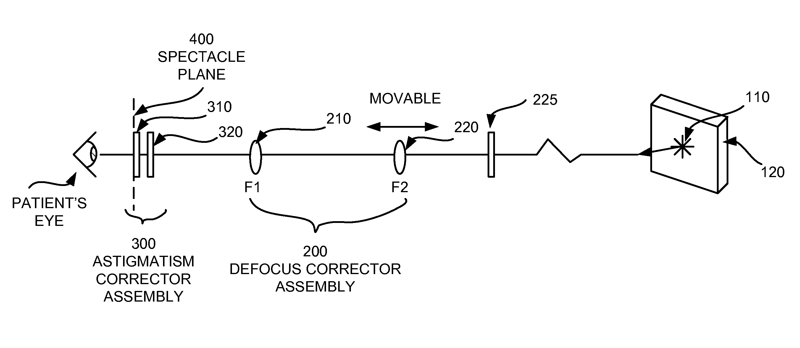
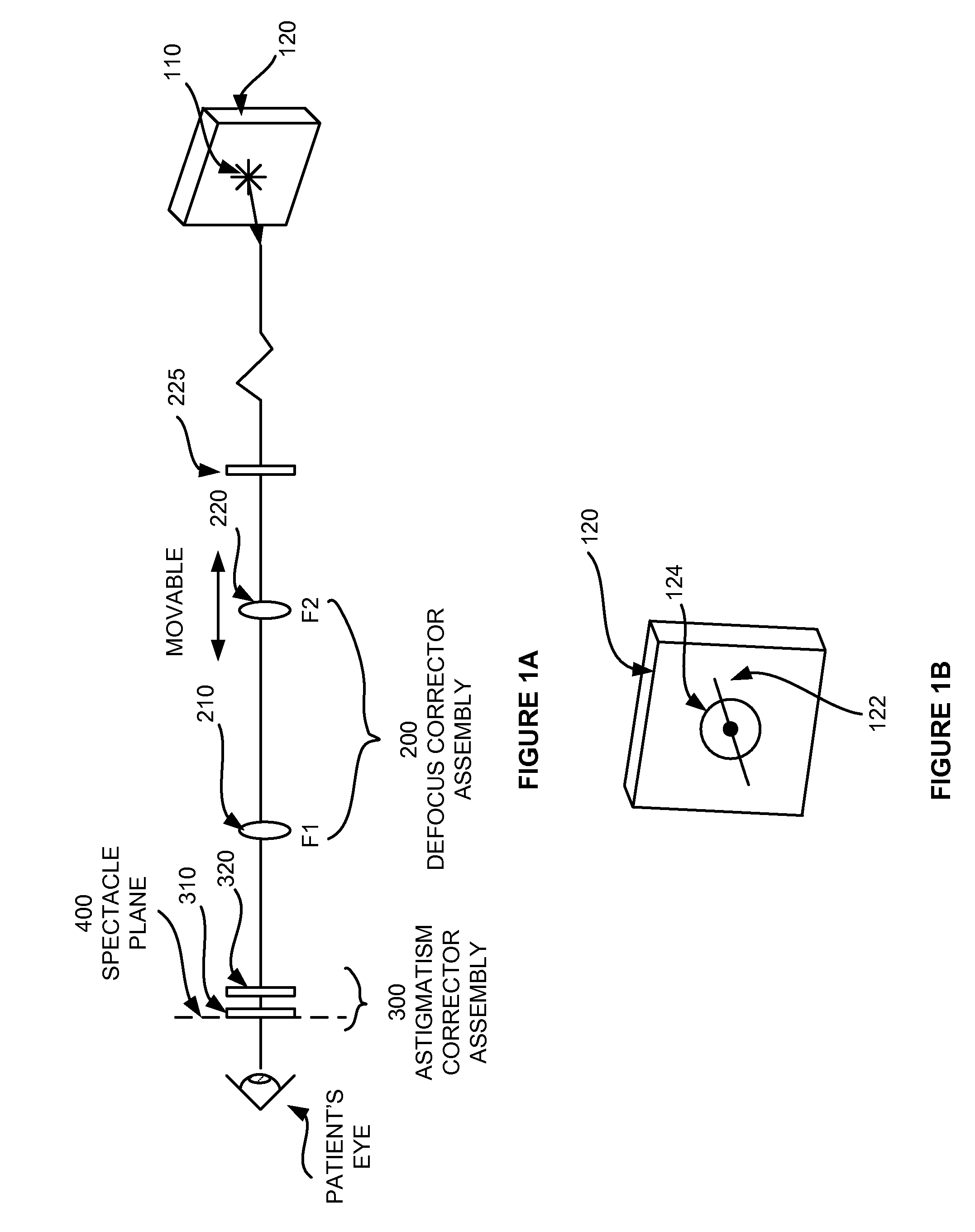
[0047] In the entire specification, the term “wavefront refraction” shall be broadly construed to include any process of providing wavefront compensation to a patient's eye, while the patient is looking at a target. A “wavefront refractor” is a device which an eye care professional may use to perform refraction that includes correcting higher order aberrations of the eye, or sometimes referred to as higher order refractive errors. The “+ / −” is also used herein before the second index of Zernike functions to represent a grouping of the pair of Zernike polynomials that have a same first index, wherein the second index has opposite sign. For example, the pair of Trefoil, Z(3,−3) and Z(3,3) are to be paired, and Z(3,+ / −3) shall designate a combination of the two Trefoils in an adjustable wave plate configuration. The term wave plate shall mean an optical plate that has the property of inducing an optical path difference profile. When a light wave passes the plate, the spatial profile ac...


PUM


Abstract

A wavefront device produces adjustable amplitudes in optical path differences and adjustable axis orientation angles. two substantially identical wave plates have a wavefront profile of at least the third order Zernike polynomial function which are not circularly symmetric, as denoted by Z(i,j) where i≧3 and j≠0. The wave plates are mounted in rotatable mounts with their optical centers substantially aligned with each other. An subjective wavefront refraction instrument and method are provided to correct low and high order aberrations of the eye, using the adjustable wave plates that have astigmatism and higher order Zernike function optical path difference wavefront profiles.

Description

PRIORITY [0001] This application claims the benefit of priority to U.S. provisional patent application No. 60 / 746,772, filed May 8, 2006, and is a Continuation in Part (CIP) of U.S. patent application Ser. No. 11 / 675,079, filed Feb. 14, 2007, which claims priority to U.S. provisional patent application No. 60 / 773,758, filed Feb. 14, 2006.BACKGROUND [0002] Before the advent of the wavefront aberrometer, many patients' visual symptoms were collectively referred to as a result of “irregular astigmatism”. Increasingly, more opthalmologists and optometrists have begun measuring wavefront errors of patients' eye. A wealth of information is now available, that was not heretofore, from auto-refractor or cornea topography measurements. Use of a wavefront map as a diagnosis tool is also gaining popularity, and vision care professionals use it to explain diagnoses to patients having visual complaints. [0003] It is useful to understand the source of a problem. However, patients are most interes...

Claims


Application Information

Patent Timeline
IPC IPC(8): A61B3/02A61B3/00G02C7/02
CPCG02C7/02A61B3/036A61B3/0008A61B3/0025A61B3/032
Inventor LAI, SHUI T.
Owner LAI SHUI T
Why Eureka
Try Eureka