Submersible LED light fixture

a led light fixture and submerged technology, applied in the field of led light fixtures, can solve the problems of inefficiency of traditional light sources such as incandescent or fluorescent light sources, increase in temperature, waste of thermal energy, etc., and achieve the effect of discharging heat from the control modul

Inactive Publication Date: 2007-12-04
NEXXUS LIGHTING +1
View PDF4 Cites 114 Cited by
  • Summary
  • Abstract
  • Description
  • Claims
  • Application Information

AI Technical Summary

Problems solved by technology

Generating visible light with traditional light sources, such as incandescent or fluorescent light sources, is inefficient because thermal energy is also produced as by-product of the process.
Fixtures such as light shades or reflectors, or even the target illuminated by the light source, receive the wasted thermal energy, and consequently, rise in temperature.
In some instances, the rise in temperature can reduce the useful life of a product.
Further, the arrangement of traditional light sources are limited to designs that can withstand the wasted thermal energy.
In underwater applications, wasted thermal energy is typically dissipated into the water, however, this does not prevent the light fixtures from having a relatively short life due to this excess heat.
It is also known to use fiber-optic cables for underwater lighting, but fiber-optic lighting is expensive and difficult to install, and is not suitable for the retro-fitting of existing pools.
Additionally, the fiber-optic light fixtures are not as bright as traditional incandescent light fixtures, and are therefore not well used in pool and other underwater lighting applications.
However, single LED lights are typically not bright enough for illuminating objects or for use in pool and other underwater lighting.
Although LEDs do not generally radiate heat in the direction of the beam of light produced, implementation of LEDs for many traditional light source applications has been hindered by the amount of heat build-up within the electronic circuits of the LEDs.
This heat build-up is particularly problematic as more LEDs are added to a cluster.
Heat build-up reduces LED light output, shortens lifespan and can eventually cause the LEDs to fail.
The use of adhesive tape introduces several problems, such as the labor and time intensive process of providing tape for each individual LED.
Further, adhesive tapes are susceptible to being displaced during the assembly process, resulting in less than optimal heat dissipation.
Particular problems arise when the light fixture is intended for use underwater in a swimming pool, spa, fountain, sink or other water feature.
For example, it is not possible to use adhesive tape to connect an LED to a heat sink in a fixture designed to be submerged, because the adhesive can dissolve in water, causing the connection to the heat sink to be broken.

Method used


Image

  • Submersible LED light fixture
  • Submersible LED light fixture
  • Submersible LED light fixture

Examples


Embodiment Construction

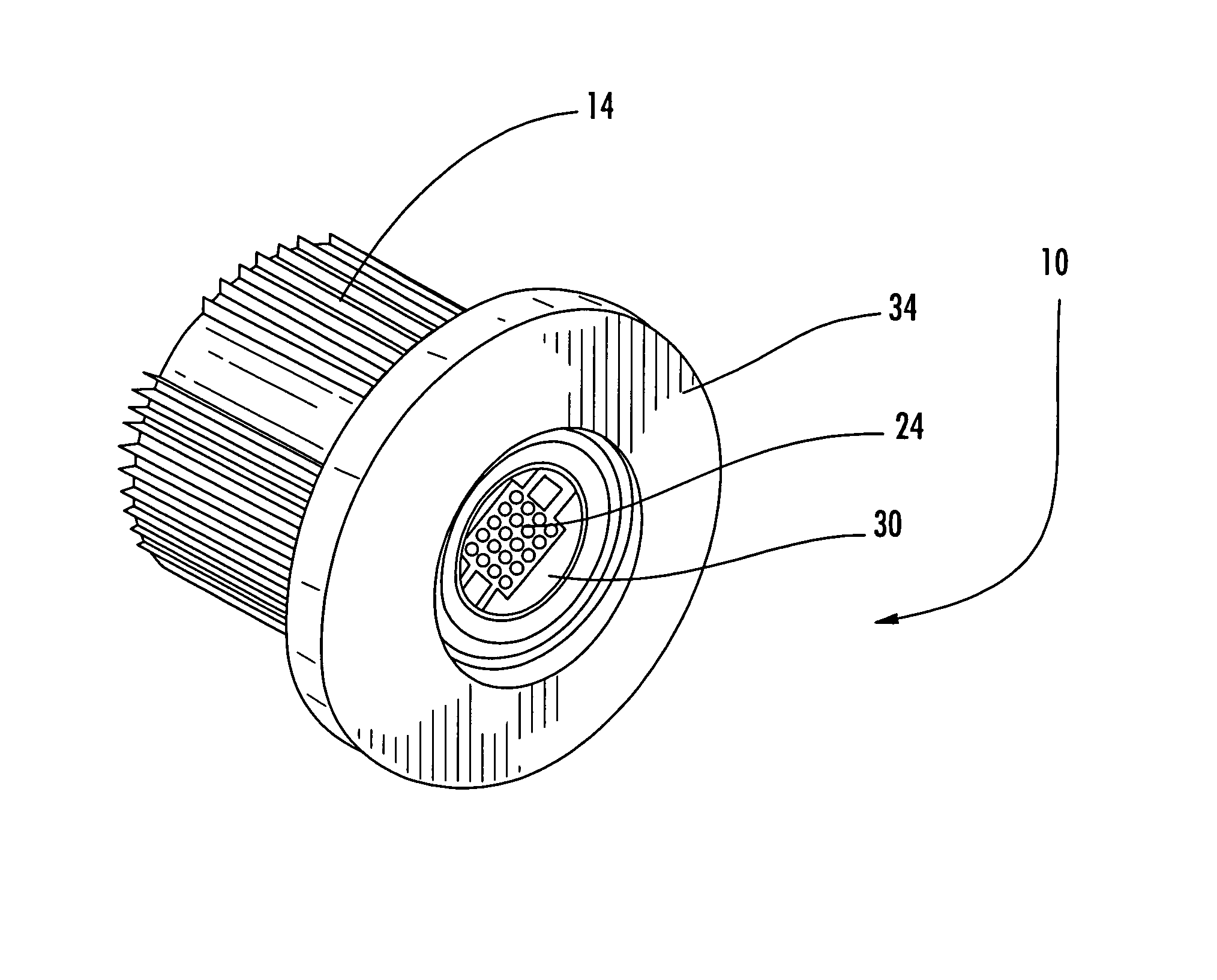
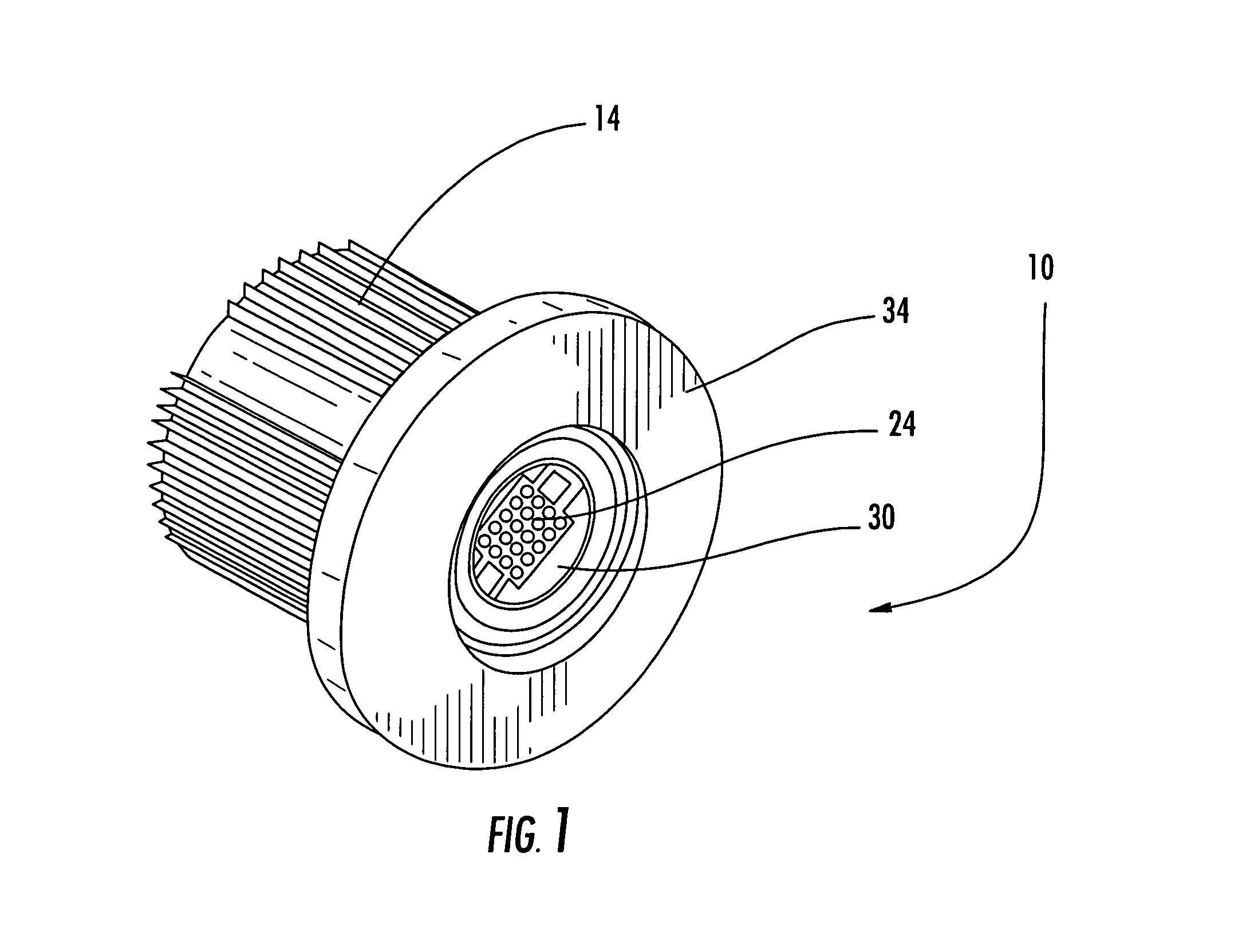
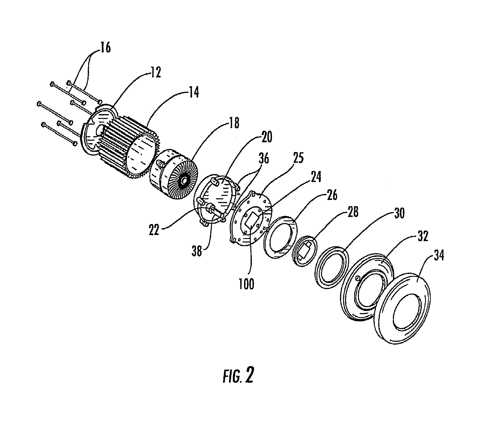
[0022]The present invention provides light emitting diode (LED) fixtures, and more particularly, submersible LED light fixtures for use in swimming pools, spas and the like. It will be appreciated that the LED fixtures are intended for use in any suitable underwater application such as swimming pools, spas, fountains, sinks, waterfalls or any other water feature, and is not limited in this regard.

[0023]An arrangement of the present invention is illustrated in the accompanying drawings. These figures show a submersible LED light fixture according to the present invention. The light fixture 10 can include a base plate 12, which may be mounted to a ribbed outer sleeve 14 by screws 16. A control module 18 is located within the sleeve 14, and the sleeve is capped by a cap 20. The cap 20 includes an aperture for an electrical connection 22 to an LED light engine 24 that is mounted on a metallic plate 25. The LED light engine 24 is protected from water by a lens arrangement including an an...


PUM


Abstract

A submersible light fixture which includes a housing, and an LED light engine mounted to a heat-conducting plate, with the heat conducting plate being supported by the housing. The housing defines an opening adjacent to the heat-conducting plate, and the opening is designed to be in fluid communication with a body of water when the light fixture is submerged such that the water acts as a heat sink to the LED light engine. In one arrangement, the opening is a gap between the heat-conducting plate and a watertight container containing a control module for the LED light engine.

Description

CROSS-REFERENCE TO RELATED APPLICATIONS[0001]Not Applicable.FIELD OF THE INVENTION[0002]This invention is directed generally to light emitting diode (LED) fixtures, and more particularly, to submersible LED light fixtures for use underwater in swimming pools, spas and the like.BACKGROUND OF THE INVENTION[0003]Generating visible light with traditional light sources, such as incandescent or fluorescent light sources, is inefficient because thermal energy is also produced as by-product of the process. The wasted thermal energy is generally directed away from the light source in the direction of the radiant beam of light. Fixtures such as light shades or reflectors, or even the target illuminated by the light source, receive the wasted thermal energy, and consequently, rise in temperature. In some instances, the rise in temperature can reduce the useful life of a product. Further, the arrangement of traditional light sources are limited to designs that can withstand the wasted thermal e...

Claims


Application Information

Patent Timeline
Patent Type & Authority Patents(United States)
IPC IPC(8): F21V33/00
CPCF21V23/02F21V29/004F21V29/89F21V29/58F21V29/70F21V29/773F21S8/024F21V31/00F21W2121/02F21Y2101/02F21Y2105/001F21W2131/401F21Y2105/10F21Y2115/10F21V29/51
Inventor KOREN, PAULARCHER, ROYFABER, STEPHENBAUER, MICHAEL
Owner NEXXUS LIGHTING
Why Eureka
Try Eureka