[0017]These and other aspects, features, and advantages of this invention will become apparent from the following detailed description when taken in conjunction with the accompanying drawings, which are a part of this disclosure and which illustrate, by way of example, principles of this invention.
[0018]The accompanying drawings facilitate an understanding of the various embodiments of this invention. In such drawings:
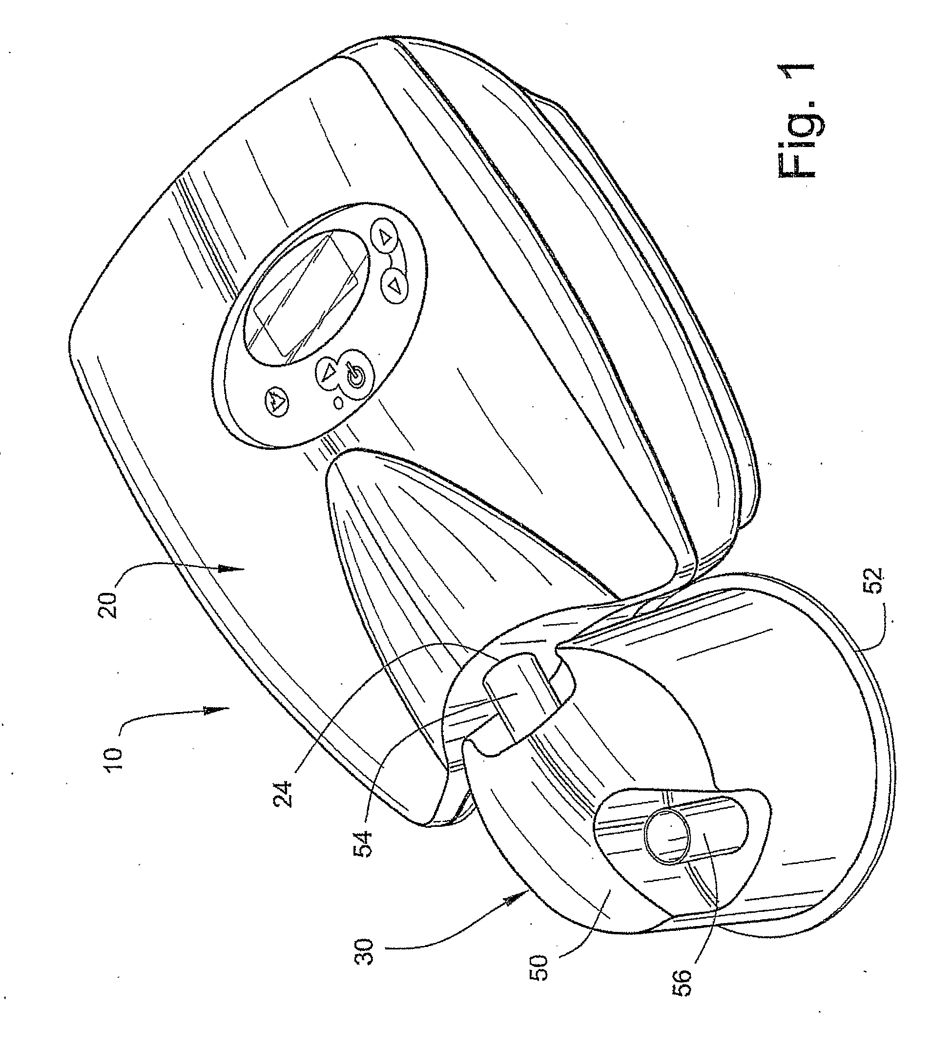
[0019]FIG. 1 is a perspective view of a CPAP device according to an embodiment of the invention;
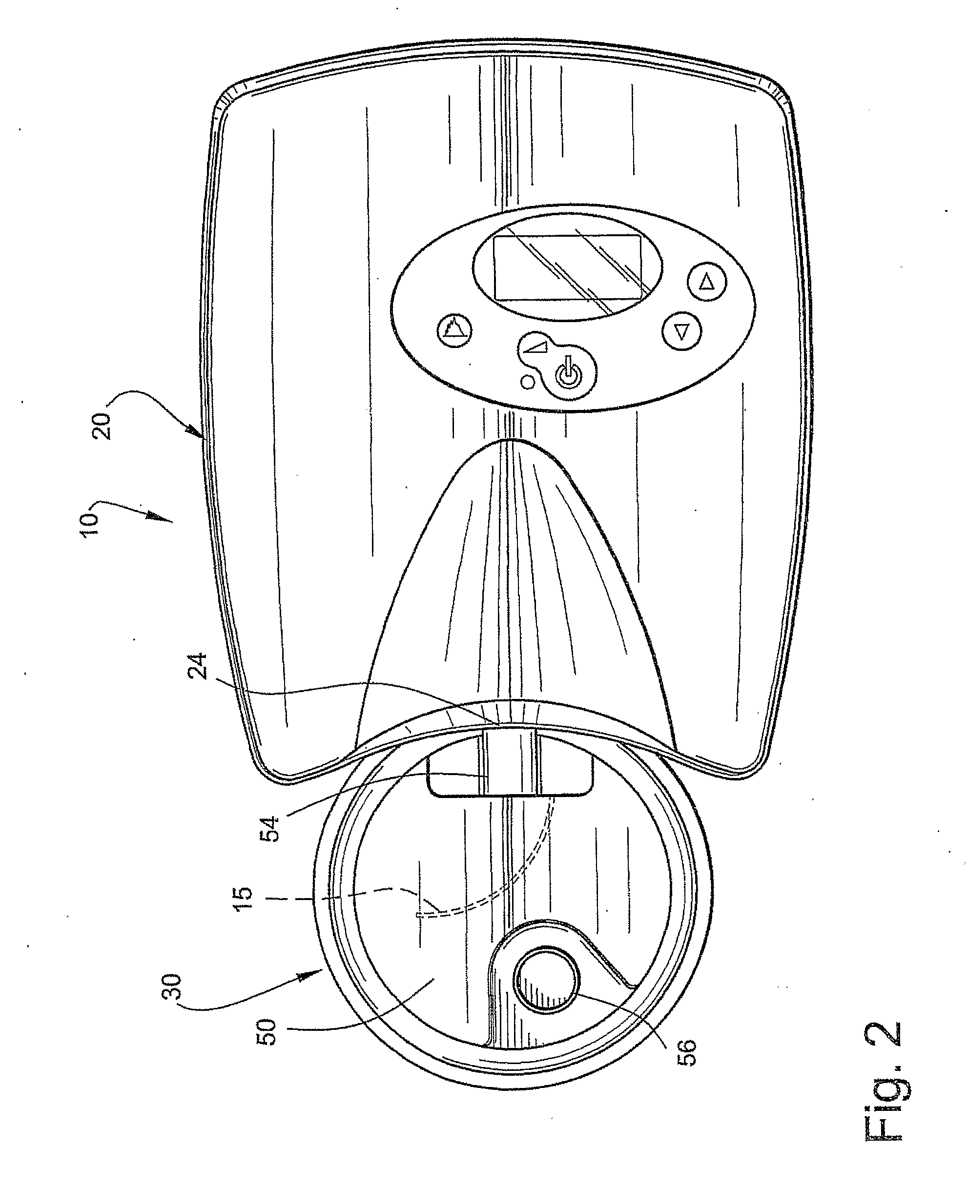
[0020]FIG. 2 is a top view of the CPAP device shown in FIG. 1;
[0021]FIG. 3 is a side view of the CPAP device shown in FIG. 1;
[0022]FIG. 4 is an end view of the CPAP device shown in FIG. 1;
[0023]FIG. 5 illustrates a blower with a seal / connector according to an embodiment of the present invention;
[0024]FIG. 6 illustrates the blower and seal / connector of FIG. 5 in an exploded position;
[0025]FIG. 7 is a cross section along section 7-7 of FIG. 5;
[0027]FIGS. 8B-8C illustrate a seal / connector according to an embodiment of the present invention in use;
[0027]FIGS. 8B-8C illustrate a seal / connector according to an embodiment of the present invention in use;
[0028]FIGS. 9-12 illustrate a cradle according to an embodiment of the present invention using a catch to secure the humidifier tub;
[0029]FIG. 13 illustrates a cradle according to another embodiment of the present invention using a sliding docking portion to secure the humidifier tub;
[0030]FIGS. 14A, 14B, and 15 illustrate a cradle according to another embodiment of the present invention using a pivoting docking portion to secure the humidifier tub;
[0031]FIG. 16 illustrates a cradle according to another embodiment of the present invention using a spring-biased clamping edge to secure the humidifier tub;
[0032]FIGS. 17-22 illustrate a cradle according to another embodiment of the present invention using a pivotable front guard and a pivotable humidifier retaining portion;
[0033]FIGS. 23-25 illustrate a cradle according to another embodiment of the present invention using a front guard and at least two pressure pads;
[0034]FIG. 26 illustrates a humidifier tub secured to the cradle shown in FIGS. 23-25, the humidifier tub engaged with the seal / connector shown in FIGS. 5-7;
[0035]FIG. 27 is a cross-sectional view through the humidifier tub and cradle shown in FIG. 26;
[0036]FIG. 28 is an exploded view of a flow generator according to an embodiment of the present invention;
[0037]FIG. 29 is a
schematic drawing illustrating the general architecture of a portion of a flow generator according to an embodiment of the present invention; and
[0038]FIG. 30 is a
schematic exploded view of a portion of a flow generator according to an embodiment of the present invention.
[0019]FIG. 1 is a perspective view of a CPAP device according to an embodiment of the invention;
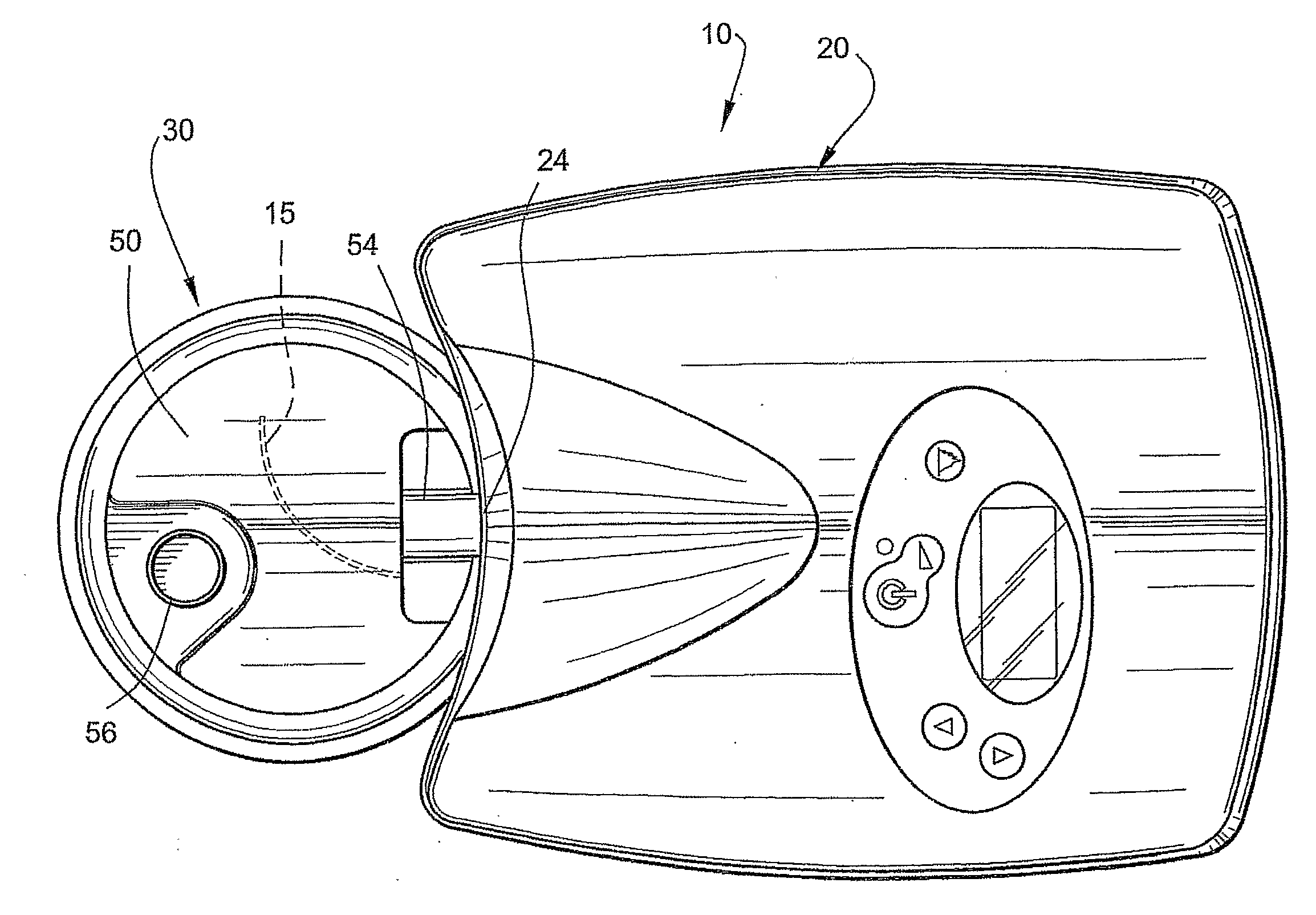
[0039]FIGS. 1-4 illustrate a CPAP device 10 according to an embodiment of the present invention. As illustrated, the CPAP device 10 includes a flow generator 20 and a humidifier 30 adapted to be coupled to the flow generator 20.
[0040]The humidifier may be connected to the flow generator using loop-back power and communication cables between the humidifier and the flow generator. In an alternative, the humidifier and the flow generator may communicate using a
fiber optic or
infrared communication
system between the flow generator and the humidifier. This
system may detect the presence of the humidifier tub and provide communication and power between the devices via transmitters and receivers.
[0041]The humidifier 30 includes a humidifier tub 50 having a base plate 52 sealed to the bottom of the tub 50 and a heater element that may be formed as part of a cradle unit 40 (see FIG. 9). The heater element may also be formed as an integral part of the base plate or otherwise separate from the cradle. The tub 50 includes an inlet 54 adapted to be in fluid communication with (i.e. not necessarily directly) the outlet 24 of the flow generator 20, and an outlet 56 adapted to be connected to an air delivery conduit. The air delivery conduit includes one end coupled to the outlet 56 of the tub 50 and an opposite end coupled to a patient interface. The patient interface comfortably engages the patient's face and provides a seal. The patient interface may have any suitable configuration as is known in the art, e.g., full-face
mask, nasal
mask, oro-nasal
mask, mouth mask,
nasal prongs, etc.
[0042]The tub 50 and base plate 52 define a chamber that is adapted to receive a volume of water, e.g., several hundred milliliters. The inlet 54 and the outlet 56 are both in communication with the chamber. In use, a supply of pressurized air from the flow generator 20 enters the inlet 54 of the tub 50 and collects
moisture through contact with the water within the tub 50 before continuing on to the outlet 56 and to the patient via the air delivery conduit.
[0043]As best shown in FIG. 2, the tub 50 may include a curved baffle 15 adjacent the outlet end of the inlet 54 to smoothly change the direction of the air flow by gently guiding the air flow around the tub 50 while limiting the loss of pressure. Also, the base plate 52 may be in the form of a
heat conducting base plate. Specifically, the base plate 52 may be formed of a heat conducting material, e.g., aluminum sheet.
[0044]In an embodiment, the humidifier 30 and tub 50 may be structured such as the humidifier and tub described in U.S.
Patent Application No. 60 / 707,949, entitled “Humidifier Tub For CPAP Device”, filed Aug. 15, 2005, the contents of which are incorporated in its entirety by reference herein. Also, in an embodiment, the flow generator 20 may be structured and controlled such as the flow generator described in U.S.
Patent Application No. 60 / 707,951, entitled “Low Cost CPAP Flow Generator and Humidifier
Assembly”, filed Aug. 15, 2005, the contents of which are incorporated in its entirety by reference herein.
[0045]FIGS. 5-7 illustrates a connector 60 according to an embodiment of the present invention. The connector 60 interconnects the outlet 24 of the flow generator 20 and the inlet 54 of the tub 50. Moreover, the connector 60 provides a pressure-activated or ‘self-energizing’
face seal that provides a seal between the flow generator 20 and the tub 50. The seal accommodates misalignment and manufacturing tolerances as described below.
[0046]As illustrated, the connector 60 provides a channel 62 (FIG. 7) to deliver pressurized air from the flow generator 20 to the humidifier tub 50. In the illustrated embodiment, the connector 60 is removably attached to the flow generator 20 and is structured to sealingly engage with the inlet 54 of the tub 50.
[0047]As best shown in FIG. 7, the connector 60 includes two components that are coupled to one another. Specifically, the connector 60 includes a firm frame attaching portion 64 and a flexible sealing portion 66. The firm frame attaching portion 64 is preferably constructed of a plastic material and includes an attachment structure that enables secure attachment to the outlet 24 of the flow generator 20. For example, the attachment structure may be in the form of a snap-fit clip that includes one or more protrusions 68 adapted to engage within a corresponding groove 70 provided in the outlet 24 with a snap fit, as shown in FIG. 7. However, the attachment structure may have other suitable configurations.

