
Pump connector system

a technology of connectors and pumps, applied in the direction of electrical apparatus casings/cabinets/drawers, non-positive displacement fluid engines, instruments, etc., can solve the problems of high water float, no convenient way to incorporate a back-up, or to energize displaced alarms

Inactive Publication Date: 2007-12-11
METROPOLITAN IND
View PDF10 Cites 84 Cited by
  • Summary
  • Abstract
  • Description
  • Claims
  • Application Information

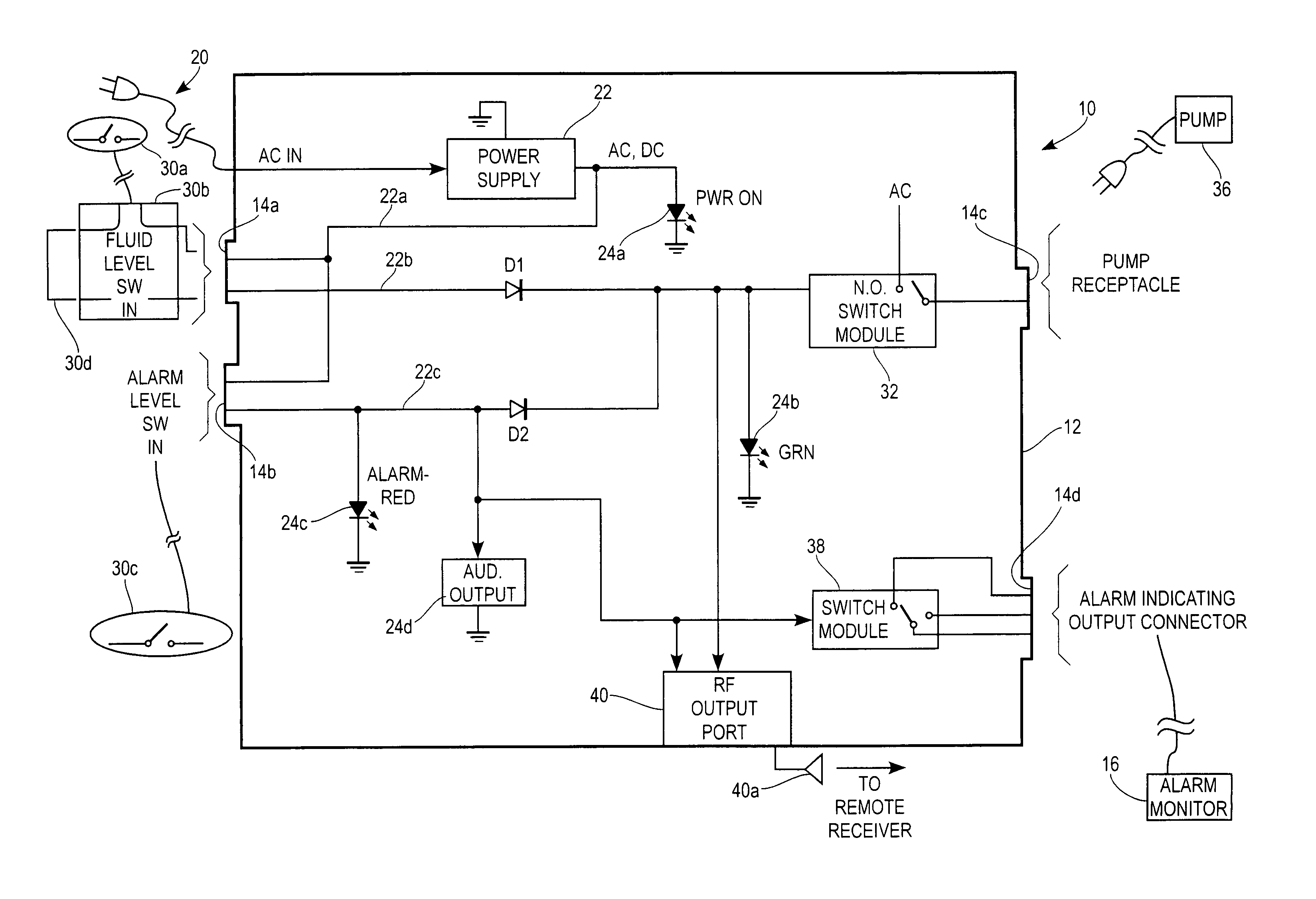
AI Technical Summary

Problems solved by technology

Further, there is no convenient way to incorporate a back-up, high water float, or to energize displaced alarms.

Method used


Image

  • Pump connector system
  • Pump connector system

Examples


Embodiment Construction

[0009]While embodiments of this invention can take many different forms, specific embodiments thereof are shown in the drawings and will be described herein in detail with the understanding that the present disclosure is to be considered as an exemplification of the principles of the invention, as well as the best mode of practicing same, and is not intended to limit the invention to the specific embodiment illustrated.

[0010]Pump control units which embody the present invention can be used with any appropriately sized pump and with a switch having a piggy-back plug. As those of skill in the art understand, in such configurations, the pump motor and switch cable are separate from one another.

[0011]A pump control unit which embodies the present invention incorporates a housing. The housing carries a fluid level indicating switch receptacle, an alarm switch receptacle, a pump receptacle and an alarm indicating output receptacle. The unit can be energized by locally available AC power. ...


PUM


Abstract

A single pump control unit can be coupled to first and second float switches and a pump for purposes of removing fluid from a region such as a sump. A supplemental set of contacts can be provided to couple an alarm indicating signal to a remote alarm. An alarm state can also be transmitted wirelessly.

Description

FIELD OF THE INVENTION[0001]The invention pertains to control units for pumps.BACKGROUND OF THE INVENTION[0002]Control units for use with various types of fluid pumps, for example, sump pumps, are known. One such system has been disclosed in Kochan, Jr. U.S. Pat. No. 5,449,274 entitled “Sump System Having Timed Switching of Plural Pumps” which issued Sep. 12, 1995. The '274 patent is owned by the assignee hereof and is incorporated herein by reference.[0003]The system of the '274 patent provides for alternating control of first and second different pumps. Not all installations need multiple pumps.[0004]In another configuration, float switches are known which have a so-called piggy-back plug. The plug includes a socket for a plug for a pump motor. The float switch is in series with the motor. When the float indicates high water the float switch closes and the motor is energized. Pumping continues until the level falls enough to open circuit the switch.[0005]While the above configurat...

Claims


Application Information

Patent Timeline
Patent Type & Authority Patents(United States)
IPC IPC(8): G08B21/00
CPCF04D15/0218F04D15/0077
Inventor KOCHAN, JR., JOHN R.
Owner METROPOLITAN IND
Learn More