Method and apparatus for replay of historical data

a historical data and replay technology, applied in the field of replaying historical data, can solve the problems of many typical systems for monitoring remote locations and equipment, many deficiencies, and many end-users limited to a tabular view of values with few visual clues

Inactive Publication Date: 2009-03-05
AMERICA POWER CONVERSION CORP
View PDF99 Cites 24 Cited by
  • Summary
  • Abstract
  • Description
  • Claims
  • Application Information

AI Technical Summary

Problems solved by technology

However, many typical systems for monitoring remote locations and equipment suffer from deficiencies associated with displaying and representing data to end-users.
End-users are typically limited to a tabular view of values with few visual clues as to the meaning of those values.
With such systems, alarms may be missed.
Further, users may not notice trending values until an alarm or damage has occurred.
In addition, such display methods make analysis of trends and causality difficult.
Failure to understand the cause of a failure or alarm may lead to repeated damage and costly equipment failures.
As such, many typical monitoring systems suffer from deficiencies in representing data.

Method used


Image

  • Method and apparatus for replay of historical data
  • Method and apparatus for replay of historical data
  • Method and apparatus for replay of historical data

Examples


Embodiment Construction

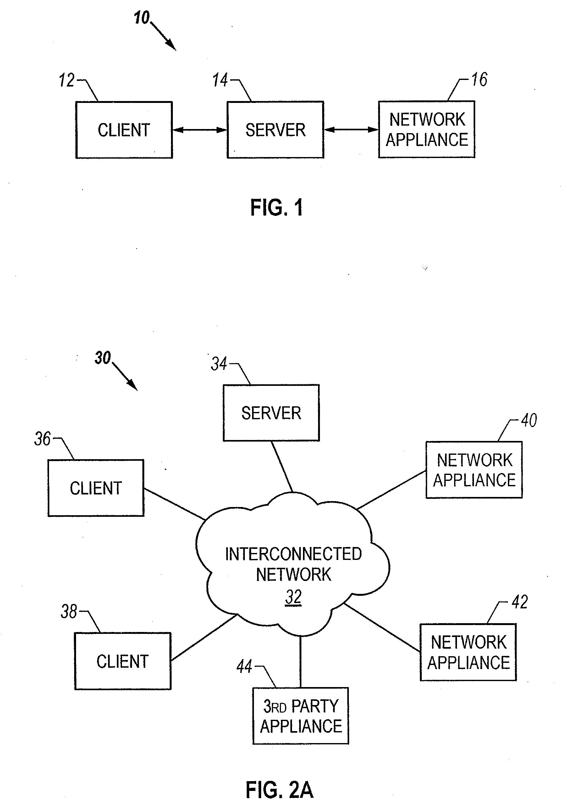
[0046]FIG. 1 is a schematic block diagram of the system according to the invention. The system 10 has a server, a client 12 and a network appliance 16. The server 14 is connected to one or more network appliances 16 through an interconnected network. The server 14 may function to transfer sensor data from the network appliance 16 and transfer configuration data to the network appliances 16. The server 14 is also connected to a client machine 12. The client machine 12 may access, display and / or manipulate data stored on the server 14. In this manner, the client 12 may remotely monitor network appliances 16 and the client 12 may reconfigure the network appliances 16.

[0047]The client 12 may be connected to the server 14 through an interconnected network. Further, the server 14 may be connected to the network appliance 16 through an interconnected network. The interconnected network may take various forms. These forms may include a global network, wide area network, local area network, ...


PUM


Abstract

The invention is directed to a system and method for displaying data associated with network appliances. Icons may be arranged in a display area in accordance with a characteristic associated with the network appliances. This characteristic may be related to location, alarm state, sensor value, or others. Further, the icons may display visual indication associated with network appliance parameters. Moreover, the icons may be superimposed on a graphical element. This element may be a map, blueprint, image, or plot. Further, a set of historical data may be replayed through the display by altering the visual indications of the icons and the graphical element in accordance with a sequence of values contained in the historical data.

Description

RELATED APPLICATIONS[0001]This application is a continuation-in-part of U.S. patent application Ser. No. 09 / 429,504, filed Oct. 27, 1999 entitled: “METHOD AND SYSTEM FOR MONITORING COMPUTER NETWORKS AND EQUIPMENT”, and is incorporated herein by reference in its entirety.[0002]This application is a continuation-in-part of U.S. patent application Ser. No. 10 / 057,563, filed Jan. 25, 2002 entitled: “METHOD AND SYSTEM FOR A SET OF NETWORK APPLIANCES WHICH CAN BE CONNECTED TO PROVIDE ENHANCED COLLABORATION, SCALABILITY, AND RELIABILITY”, which claims priority of U.S. provisional Application No. 60 / 264,445, filed Jan. 26, 2001 entitled: “METHOD AND SYSTEM FOR A SET OF NETWORK APPLIANCES WHICH CAN BE CONNECTED TO PROVIDE ENHANCED COLLABORATION, SCALABILITY, AND RELIABILITY and is incorporated herein by reference in its entirety.[0003]This application claims priority of U.S. provisional Application, No. 60 / 279,059, filed Mar. 27, 2001 entitled: “SENSOR PLAYBACK SYSTEM AND METHOD”, and is inc...

Claims


Application Information

Patent Timeline
Patent Type & Authority Applications(United States)
IPC IPC(8): G06F3/048G06F15/16G06F15/173
CPCH04L12/2803H04L69/329H04L12/44H04L41/0853H04L41/0856H04L43/045H04L43/065H04L43/0817H04L43/12H04L2012/2841H04L2012/2845H04L67/025H04L67/12H04L67/02H04L12/2825
Inventor CHILDERS, SLOANMORAN, MIKEELDERTON, JOHNMEDFORD, MITCH
Owner AMERICA POWER CONVERSION CORP
Why Eureka
Try Eureka