

Apparatus and methods for deployment of vascular prostheses
- Summary
- Abstract
- Description
- Claims
- Application Information
AI Technical Summary
Benefits of technology
Problems solved by technology
Method used
Image

Examples
first embodiment
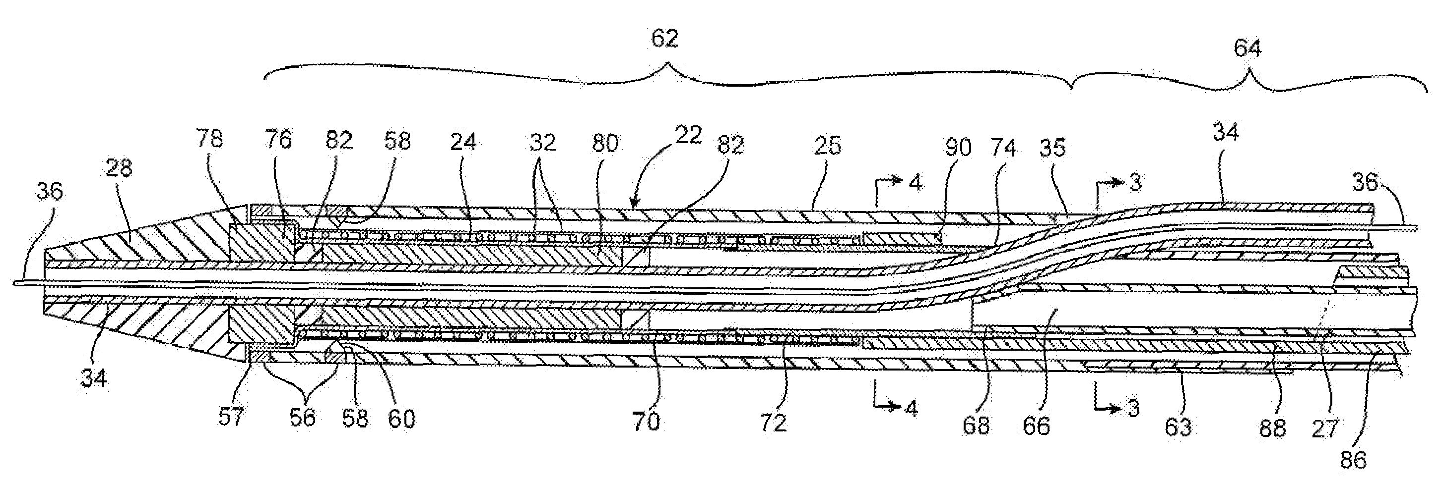
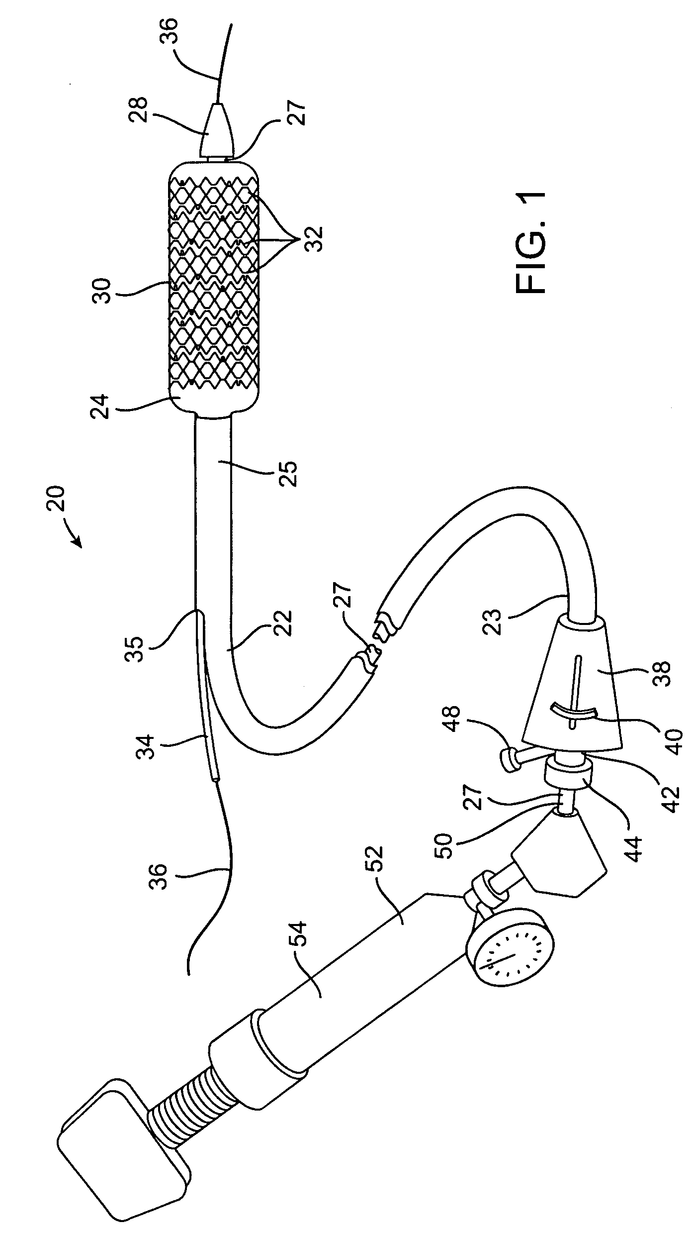
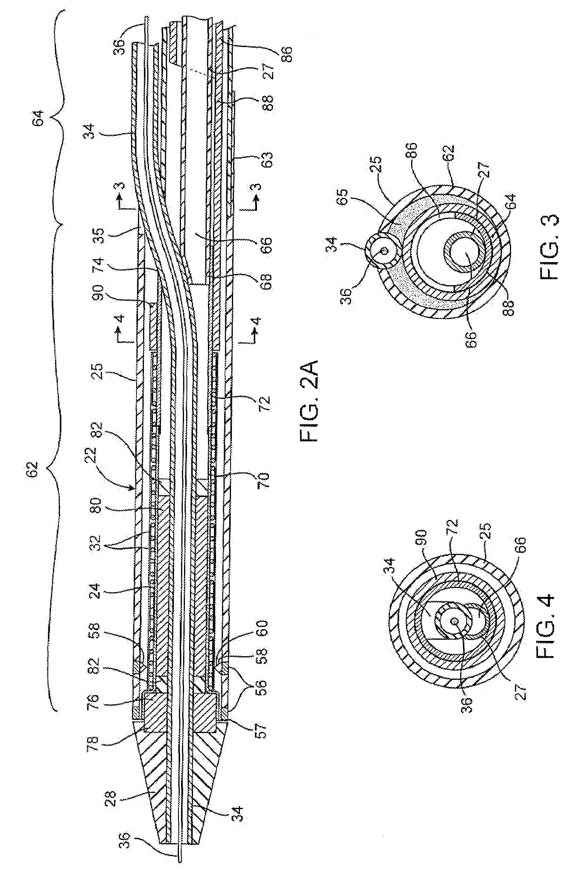
[0046]a stent delivery catheter according to present invention is illustrated in FIG. 1. Stent delivery catheter 20 includes a catheter body 22 comprising an outer sheath 25 slidably disposed over an inner shaft 27. An expandable member 24, preferably an inflatable balloon (shown in an inflated configuration), is mounted to inner shaft 27 and is exposed by retracting sheath 25 relative to inner shaft 27. A tapered nosecone 28, composed of a soft elastomeric material to reduce trauma to the vessel during advancement of the device, is mounted distally of expandable member 38. A stent 30, which preferably comprises a plurality of separate or separable stent segments 32, is disposed on expandable member 24 for expansion therewith. A guidewire tube 34 is slidably positioned through a guidewire tube exit port 35 in sheath 25 proximal to expandable member 24. A guidewire 36 is positioned slidably through guidewire tube 34, expandable member 24, and nosecone 28 and extends distally thereof....
second embodiment
[0102]FIGS. 6A-6B illustrate a stent segment 32 according to the invention. In FIG. 6A, a portion of stent segment 32 is shown in a planar shape for clarity. Similar to the embodiment of FIG. 5A, stent segment 32 comprises two parallel rows 122A, 122B of I-shaped cells 124 formed into a cylindrical shape around axial axis A. Cells 124 have upper and lower axial slots 126 and a connecting circumferential slot 128. Upper and lower slots 126 are bounded by upper axial struts 130, lower axial struts 132, curved outer ends 134, and curved inner ends 136. Circumferential slots 128 are bounded by outer circumferential strut 138 and inner circumferential strut 140. Each I-shaped cell 124 is connected to the adjacent I-shaped cell 124 in the same row 122 by a circumferential connecting strut 142. Row 122A is connected to row 122B by the merger or joining of curved inner ends 136 of at least one of upper and lower slots 126 in each cell 124.
[0103]One of the differences between the embodiment ...
PUM
 Abstract
Description
Claims
Application Information