Printed circuit board having structure for preventing coating liquid overflow

Active Publication Date: 2018-07-26
ALPS ALPINE CO LTD
View PDF2 Cites 0 Cited by
  • Summary
  • Abstract
  • Description
  • Claims
  • Application Information

AI Technical Summary

Benefits of technology

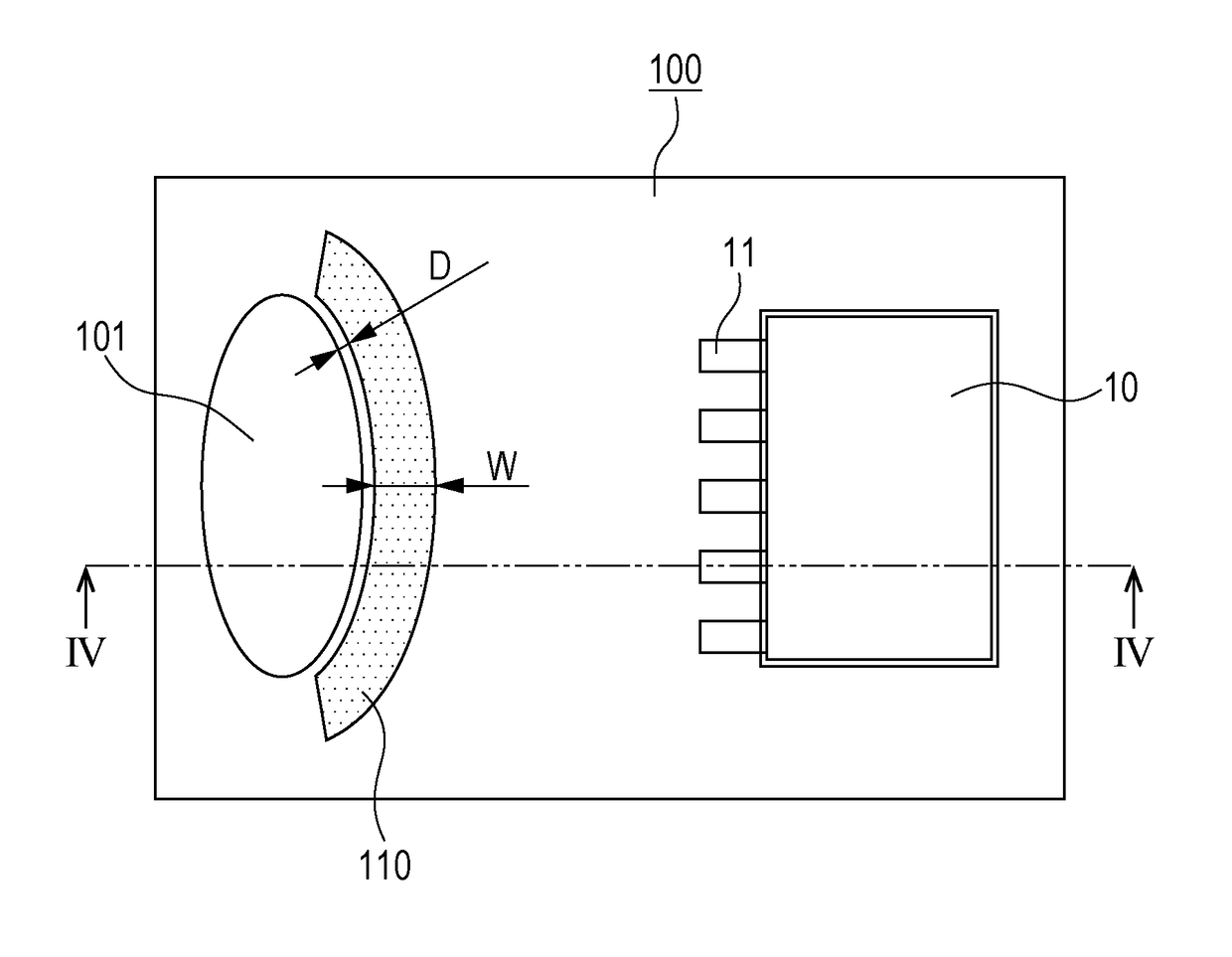
The present disclosure provides a printed circuit board that has a structure that can prevent a coating liquid from entering a connection hole after it is applied. The printed circuit board includes a land region adjacent to the connection hole that has a structure to limit the flow of the coating liquid. This prevents the coating liquid from entering the connection hole and potentially causing damage or malfunction. The land region and protrusion portion are positioned in a way that maximizes the use of space on the printed circuit board. The width and position of the land region, as well as the height and shape of the protrusion portion, are limited within specific ranges to efficiently utilize space and prevent the coating liquid from entering the connection hole.

Problems solved by technology

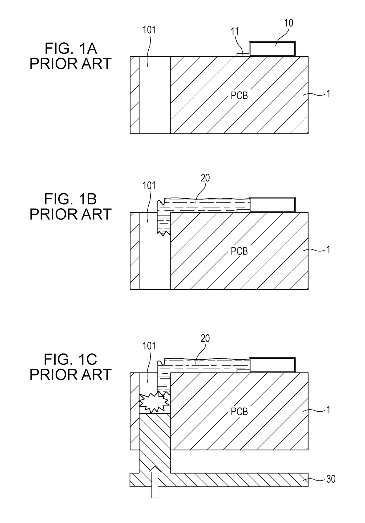
In a conventional printed circuit board (PCB), there is the possibility that a short-circuit will be generated due to ion migration (a lead growth phenomenon) in the printed circuit board in a high temperature and high humidity environment.
In addition, in the printed circuit board on which the micro control unit is mounted, one or more connection holes 101 are formed in order to join the micro control unit and another component to each other, and it is difficult to secure a sufficient spacing distance from the terminal 11 of the micro control unit 10.

Method used


Image

  • Printed circuit board having structure for preventing coating liquid overflow
  • Printed circuit board having structure for preventing coating liquid overflow
  • Printed circuit board having structure for preventing coating liquid overflow

Examples


Embodiment Construction

[0036]The following description is intended to convey a thorough understanding of the embodiments described by providing a number of specific embodiments and details involving a printed circuit board. It should be appreciated, however, that the present invention is not limited to these specific embodiments and details, which are exemplary only. It is further understood that one possessing ordinary skill in the art, in light of known systems and methods, would appreciate the use of the invention for its intended purposes and benefits in any number of alternative embodiments, depending on specific design and other needs.

[0037]Hereinafter, an embodiment of the present disclosure will be described in detail with reference to the drawings. Terms and words used in the present specification and claims are not to be construed as having general or dictionary meanings, but are to be construed as having meanings and concepts in line with the technical spirit of the present invention.

[0038]Thro...


PUM

PropertyMeasurementUnit
Lengthaaaaaaaaaa
Fractionaaaaaaaaaa
Structureaaaaaaaaaa

Abstract

Disclosed herein is a printed circuit board having a structure for preventing coating liquid overflow. In the printed circuit board on which an electronic component is mounted and in which a connection hole for joining the electronic component and another component to each other is formed, a land region to which lead may be applied is formed adjacent to the connection hole.

Description

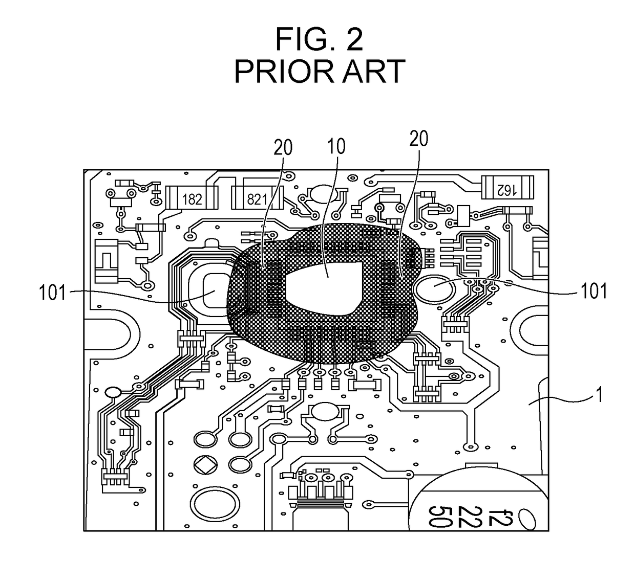
CLAIM OF PRIORITY[0001]This application claims benefit of Korean Patent Application No. 10-2017-0013031 filed on Jan. 26, 2017, the entire contents of which is incorporated herein by reference.BACKGROUND OF THE DISCLOSURE1. Field of the Disclosure[0002]Embodiments of the present disclosure relate to a printed circuit board, and more particularly, to a printed circuit board having a structure for preventing coating liquid overflow.2. Description of the Related Art[0003]In a conventional printed circuit board (PCB), there is the possibility that a short-circuit will be generated due to ion migration (a lead growth phenomenon) in the printed circuit board in a high temperature and high humidity environment. In order to solve such a problem, liquid coating may be performed on the region surrounding a terminal 11 of an electronic component 10, as illustrated in FIG. 2.[0004]Meanwhile, there are a region in which coating is required and a coating prohibited region in the printed circuit b...

Claims


Application Information

Patent Timeline
IPC IPC(8): B05C11/02B05C5/02H05K3/00
CPCB05C11/02B05C5/0212H05K3/0091H05K3/284H05K2201/09909H05K2201/10977H05K2203/0759H05K1/115H05K1/184H05K2201/048
Inventor CHOI, YOUNGGILSEOK, BOSEOK
Owner ALPS ALPINE CO LTD
Why Eureka
Try Eureka