NIST traceable automated visual inspection system for an inspection of particles in solution

a technology of automated visual inspection and particle solution, which is applied in the field of injectable pharmaceutical preparation inspection, can solve the problems of imposing additional costs on the quality assurance program, contaminating particle position in a container, and inspection is completely random, and achieves accurate measurement

Active Publication Date: 2007-12-18
BUDD GERALD WALTER
View PDF2 Cites 18 Cited by
  • Summary
  • Abstract
  • Description
  • Claims
  • Application Information

AI Technical Summary

Benefits of technology

[0020]It is an object of the present invention to transform the present probabilistic detection of contaminating particles present in a container, even larger than 30 mm in diameter, into a deterministic detection and accurate measurement process
[0021]It is a further object of the present invention to provide a method to generate a uniform illumination field within liquid volume in a container to enhance the detection and measurement of contaminating particle(s).
[0024]It is a still further object of the present invention to provide a method that transforms the present random array of particles within a container into a positioned array in a defined portion of the container to be inspected with sufficient spatial resolution for the accurate determination of size and / or shape.
[0032]wherein the sensed signal is corrected for the asymmetries of the imaging system by correction means either by computation or by repositioning the detector means relative to the container, whereby a focused imaging plane is formed at the container axis and then mechanically or electro-mechanically offset closer to the imaging sensor than the center of the cross section, whereby the size of detected particles in the opposite volumes is accurately mathematically compensatible to an actual size. The lighting means provides a multiplicity of directed light emitting diodes (LED's), mounted on three of the interior walls of a cubic structure with an acrylic element placed in the center. The diffusing element has a “U” shaped channel removed along the centerline of cubic structure in which the container being tested is positioned. The “U” shaped diffusing element is designed to uniformly diffuse the light entering the container. The sample container rest in slightly recessed pocket centered on a rotational device. The center of the axis of rotation is positioned to coincide with the center of radius and width of the “U” shaped channel in the diffusing element. The channel width of the diffusing element should be approximately 1.5 times the diameter of the container being inspected. The lighting means may be adjusted to enhance the image characteristics by activating various LED lighting elements within the structure. Contaminating materials with less optical density can be enhanced in the image by reducing the radiant energy of the illumination system.
[0033]With said detector being mounted inside a sealed enclosure the critical optical components of the system can be protected from the environment. The detector is mounted in such a manner so that so that the optical path can be easily adjusted with the target area. The design of the sensor enclosure allows for the insertion of optical filter elements within the optical path of the invention.

Problems solved by technology

A false reject rate of good containers also results from the ‘soft’ accept / reject decision process.
This disproportionate false reject rate imposes additional costs on the quality assurance program.
When current commercially available automated inspection systems were evaluated according to this standard, it was determined that none could demonstrate, in a single inspection, results as secure or as selective as that achieved by human beings.
A complicating factor is that the position of a contaminating particle in a container at the start of each inspection is completely random.
Application of classical probability theory shows that particle detection security is enhanced but the discrimination of the accept / reject decision compared to manual inspection is impaired when this inspection technique is employed.
The cost for this improvement in detection probability is a four to six fold increase in the false rejection rate of the manual inspection.
However, secure detection of randomly occurring and randomly positioned particles in sealed transparent containers requires inspection of the full volume of the container.
However, with present art, the sharp image requirement cannot be achieved for the size range of containers used for pharmaceutical injectable products.
This reliance results in particle detection variability determined by the variation in the realizable illumination uniformity of the inspected container and variation of the detection capability of the system.

Method used


Image

  • NIST traceable automated visual inspection system for an inspection of particles in solution
  • NIST traceable automated visual inspection system for an inspection of particles in solution
  • NIST traceable automated visual inspection system for an inspection of particles in solution

Examples


Embodiment Construction

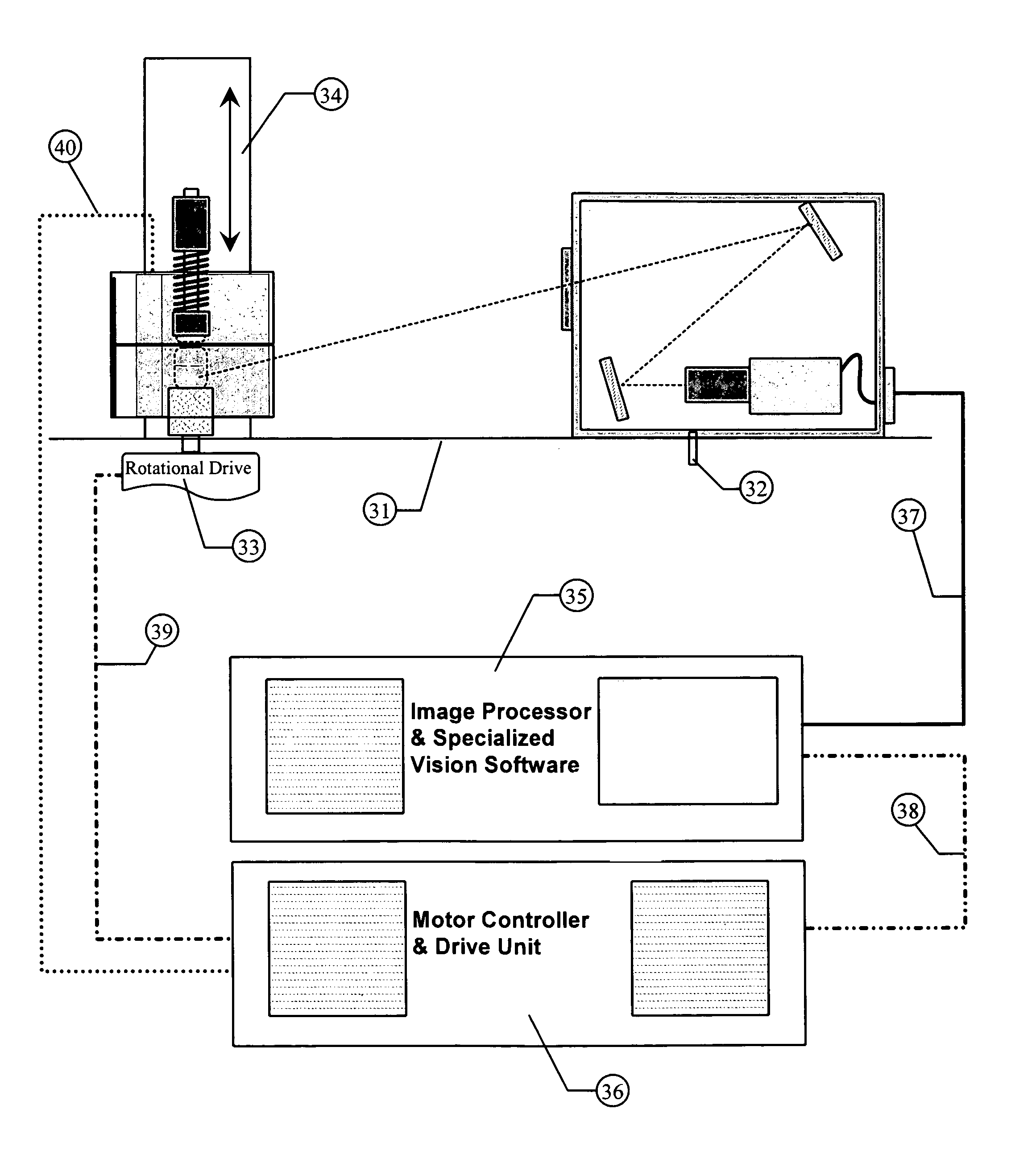
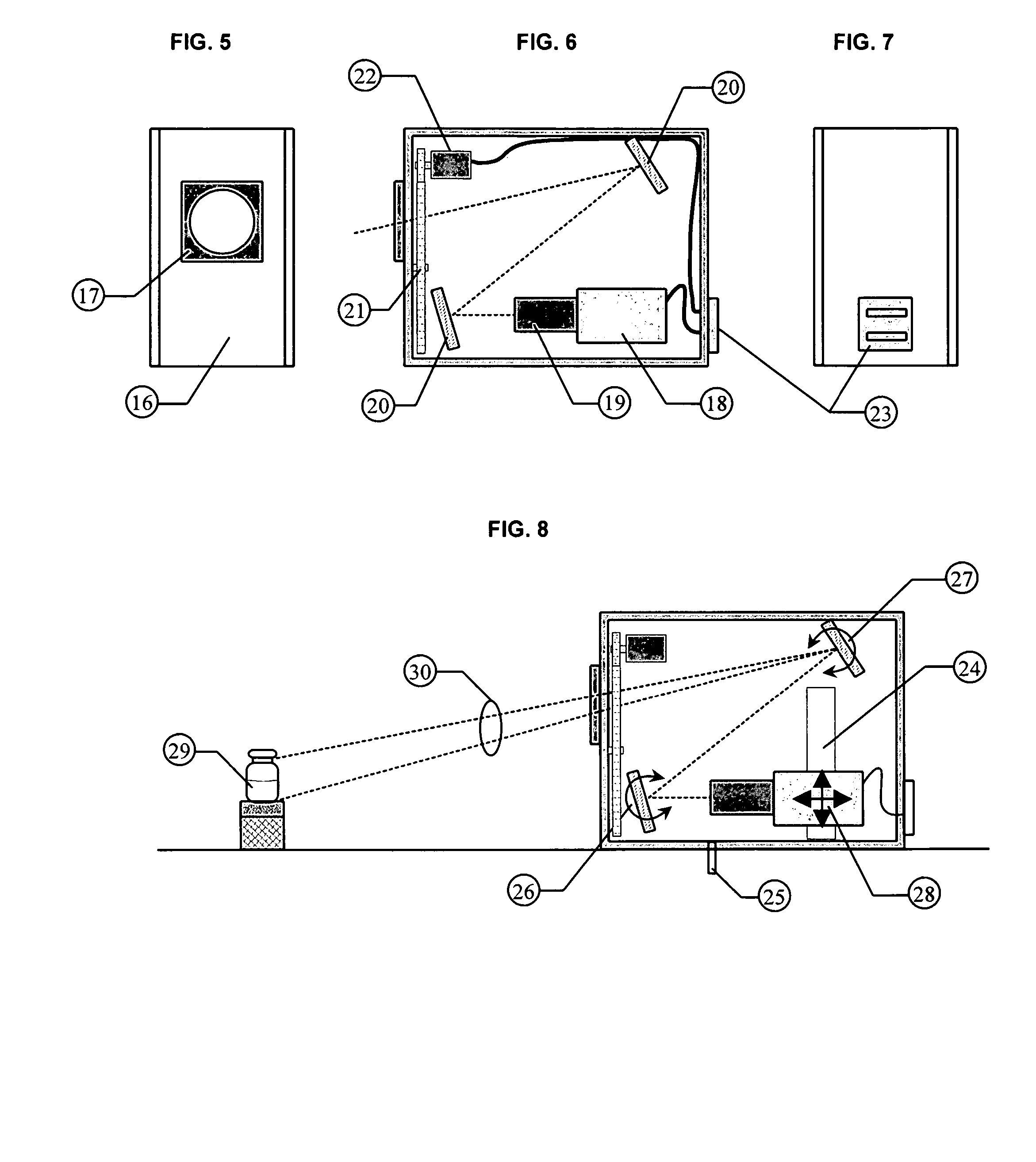
[0046]The invention is a combination of three key components configured in the proper way to determine the maximum dimension of particles in solution. The key components are an Illumination Module, a Sensor Module, and an Image Processing System with specific software. The invention has offers several unique components that allow the particle to sized accurately. The invention has many uses but is designed primarily for the detection of contamination in clear solutions like those used in the pharmaceutical products.

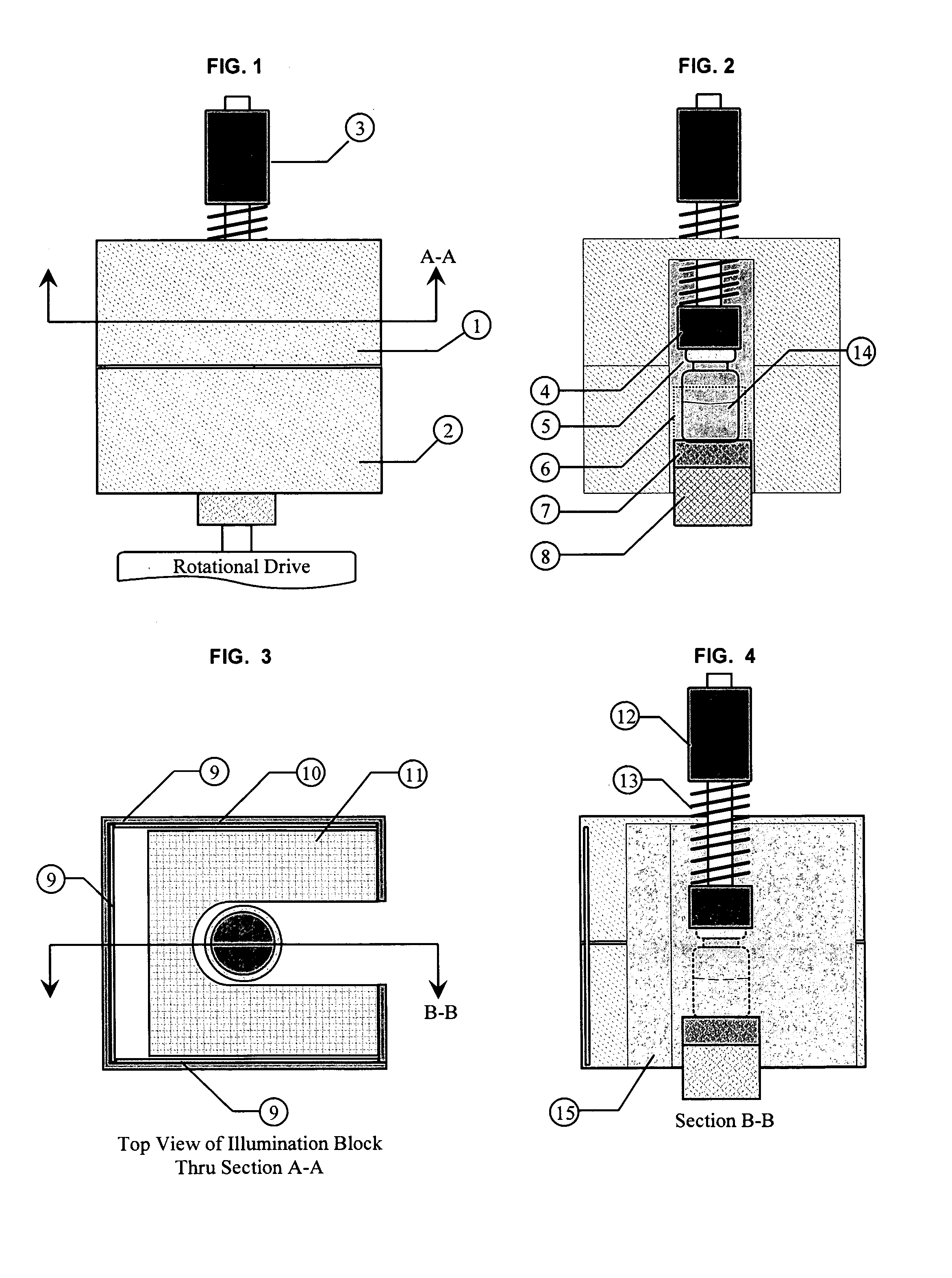
[0047]The first key component is a unique illumination system designed to provide a very uniform background for the inspection of product in cylindrical vessels such as pharmaceutical vials. The illumination system is cube shaped with a channel slightly larger than the diameter of the vessel removed from the center, hereafter we shall reference to this system as the illumination module. The basic configuration is illustrated in FIG. 1. The cube is constructed using an upp...


PUM

PropertyMeasurementUnit
diameteraaaaaaaaaa
diameteraaaaaaaaaa
diameteraaaaaaaaaa

Abstract

A method for the substantially complete detection and measurement of all particles, within a predetermined size, range, contained in an injectable solution comprising the steps of: a) rotation of the container causes substantially all of the particles in the injectable solution in the container to be set in motion; b) uniformly illuminating the background around the container with light; and c) detecting at least one of light scatter, light reflection and light extinction caused by said particles, with detectors having a depth of focus of detection in a specified volume of the container. Wherein the detectors are positioned, relative to the container whereby the optical path and field of view allows the sensor sufficient focus to view substantially all of the bottom interior surface of the container and substantially all of the solution volume within the container. The method and apparatus produces a geometric representation of the particles in the detection region, whereby the size of detected particles can be is accurately adjusted to an actual size by either calculation or by calculated offset to allow accurate measurement of particle dimensions.

Description

CROSS-REFERENCE TO RELATED APPLICATIONS[0001]I claim priority to my Provisional Application No. 60 / 518,699 with filing date Nov. 9, 2003.FIELD OF THE INVENTION[0002]This invention relates to the procedures and devices utilized in the optical inspection of transparent containers for the presence of contaminating particulate matter and particularly to inspection of injectable pharmaceutical preparations.BACKGROUND OF THE INVENTION[0003]There is a legal obligation by manufacturers of pharmaceutical injectable solutions to ensure that the product is free of ‘visible’ particle contaminants prior to their clinical use. This legal obligation can be satisfied by the use of a labor intensive and costly 100% manual inspection of injectable solutions. Less costly automated particle detection systems have been developed. However, in order to satisfy Good Manufacturing Practice, automated inspection systems must be validated prior to any pharmaceutical use. In the validation demonstration, the f...

Claims


Application Information

Patent Timeline
Patent Type & Authority Patents(United States)
IPC IPC(8): G01N15/02
CPCG01N15/0205
Inventor BUDD, GERALD WALTER
Owner BUDD GERALD WALTER
Why Eureka
Try Eureka