Small container fluid dynamics to produce optimized inspection conditions

Active Publication Date: 2005-11-10
BUDD GERALD WALTER +1
View PDF1 Cites 37 Cited by
  • Summary
  • Abstract
  • Description
  • Claims
  • Application Information

AI Technical Summary

Benefits of technology

[0031] wherein the sensed signal is corrected for the asymmetries of the imaging system by correction means either by computation or by repositioning the detector means relative to the container, whereby a focused imaging plane is formed at the container axis and then mechanically or electro-mechanically offset closer to the imaging sensor than the center of the cross section, whereby the size of detected particles in the opposite volumes is accurately mathematically compensatible to an actual size. The lighting means provides a multiplicity of directed light emitting diodes (LED's), mounted on three of the interior walls of a cubic structure with an acrylic element placed in the center. The diffusing element has a “U” shaped channel removed along the centerline of cubic structure in which the container being tested is positioned. The “U” shaped diffusing element is designed to uniformly diffuse the light enterin

Problems solved by technology

The use of the Attribute Sampling Inspection Tables with raw visible particle inspection data results in the incorrect rejection of good batches and incorrect acceptance of undesirable batches.
Although the use of Attribute Sampling Assay Tables can be made compatible with raw visible inspection data, its limited s

Method used


Image

  • Small container fluid dynamics to produce optimized inspection conditions
  • Small container fluid dynamics to produce optimized inspection conditions
  • Small container fluid dynamics to produce optimized inspection conditions

Examples


Embodiment Construction

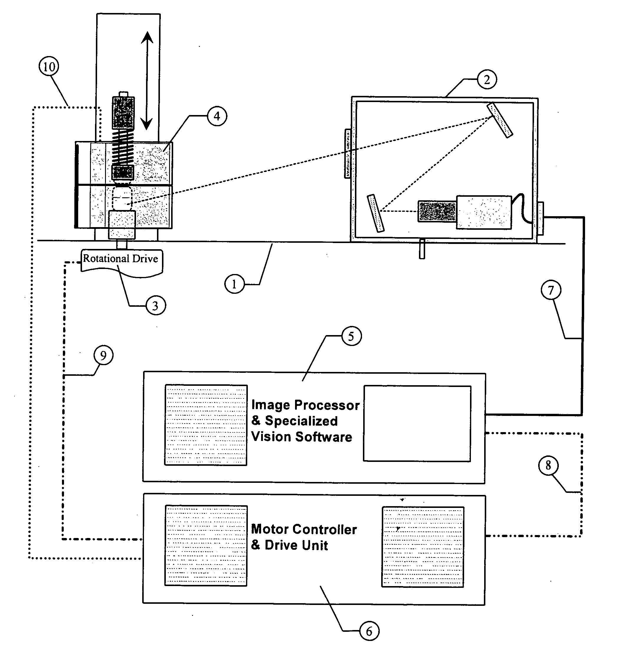
[0042] The invention is a combination of mechanical, electronic, and software components configured in the proper way to produce information that will yield repeatable measurement results. The major components and their relationship to each other are illustrated in FIG. 1. The alignment of components used for image acquisition is very important and must be referenced to level surface (item 1). A machined surface provides a excellent datum for mounting the sensor module (item 2), the rotational drive (item 3) and the illumination module (item 4). Item 2 through 4 are described in detail in the U.S. patent application Ser. No. 10 / 981,801. The sensor module contains the sensor, relay mirrors (if required), and filter elements (if required) and a method to maintain the orientation of the components with respect to each other. The sensor module was designed so that it could be replaced as a whole with a nearly identical module. The physical dimension of the sensor module would be identic...


PUM


Abstract

The generation of a desired non-linear resonance in the toroidal flow of liquid in a cylindrical injectable product is described. The resulting liquid flow pattern generated with an approximately smooth meniscus is down at the walls, across to the center of rotation, up on the center of rotation, across the meniscus to complete the pattern. The controlled flow pattern results in a predictable location for particle of varying mass and hydraulic shape. This predictability of location transforms the problem of particle detection from a chance occurrence to a deterministic task. The deterministic location of particle position is a contributor to the demonstrated capability to measure the size of visible particle range in a range from 33 μm to 1,000 μm with a median deviation of 1% and a maximum deviation from NIST dimensional accuracy of 3%.

Description

CROSS-REFERENCE TO RELATED APPLICATIONS [0001] I claim priority to my Provisional Patent Application No. 60 / 551,562 with filing date Mar. 9, 2004.DESCRIPTION [0002] 1. Field of the Invention [0003] This invention relates to the procedures and devices utilized in the optical inspection of transparent containers for the presence of contaminating particulate matter and particularly to inspection of injectable pharmaceutical preparations. [0004] 2. Background of the Invention [0005] The inspection for and elimination of visible particle contaminated containers from a batch of injectable pharmaceuticals is a United States Pharmacopeia requirement. This inspection is specified to be, whenever possible, after the product is in its final container. Evaluation that the visible particle incidence rate is within USP acceptance limits for human or veterinary use is an essential part of the injectable batch release procedure. It is also an essential prerequisite to the continuous improvement of ...

Claims


Application Information

Patent Timeline
IPC IPC(8): G01N15/14G01N21/90
CPCG01N15/1459G01N2015/1493G01N2015/1075G01N21/9027
Inventor BUDD, GERALD WALTERKNAPP, JULIUS Z.
Owner BUDD GERALD WALTER
Why Eureka
Try Eureka