
User interface for viewing performance information about transactions

a user interface and transaction technology, applied in the direction of static indicating devices, program control, instruments, etc., can solve the problems of business losing potential sales and/or customers, intranets and extranets, and it is difficult to determine which portion of software is responsible for stalling

Inactive Publication Date: 2007-12-18
CA TECH INC
View PDF20 Cites 73 Cited by
  • Summary
  • Abstract
  • Description
  • Claims
  • Application Information

AI Technical Summary

Benefits of technology

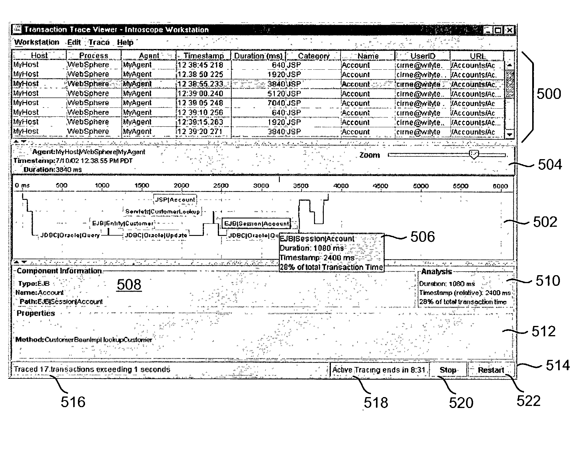
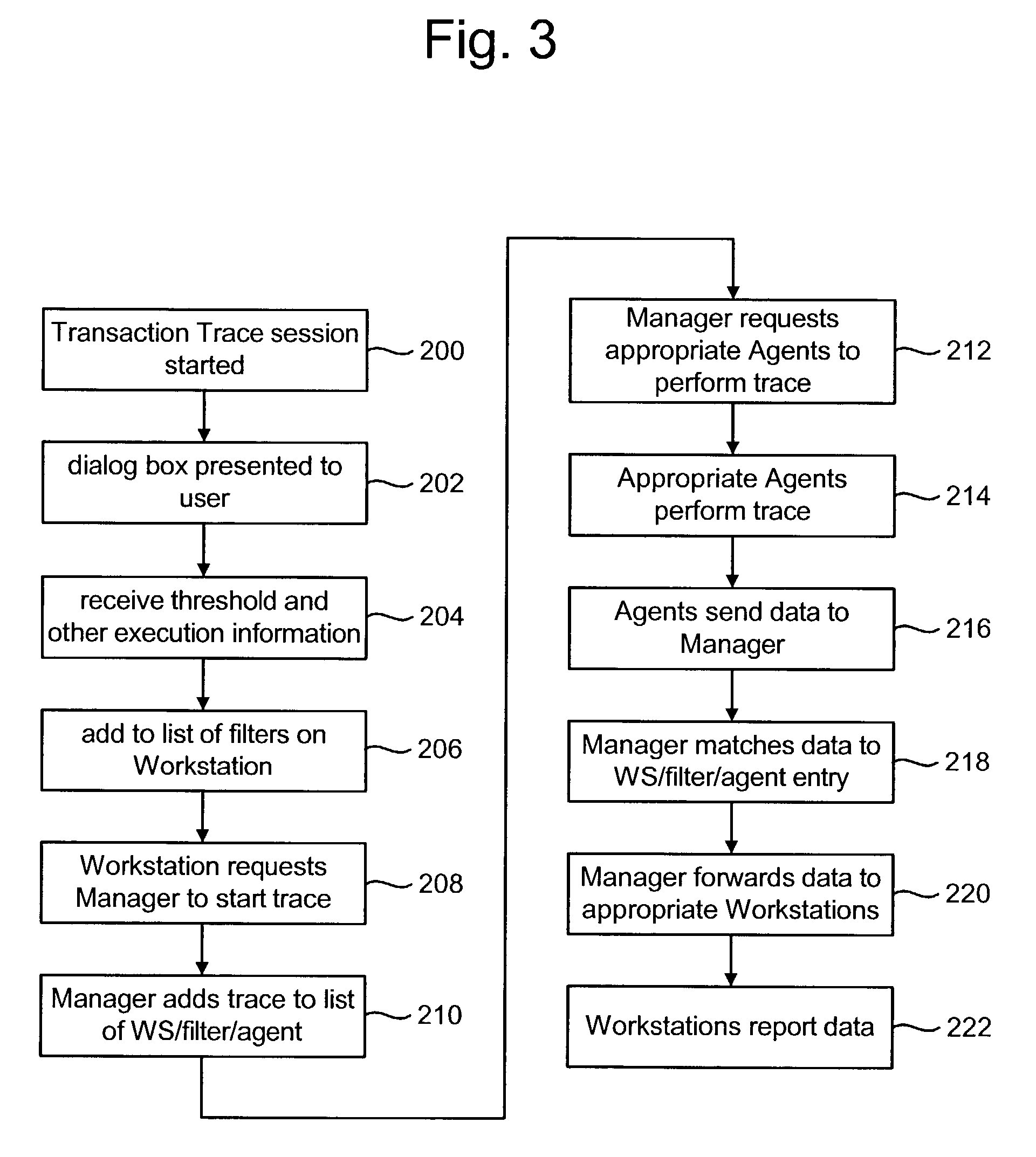
[0011]One embodiment of the user interface is used with a transaction tracer. Other embodiments are used with data providing mechanisms other than a transaction tracer. One example of a transaction tracer allows a user to specify a threshold trace period and initiate transaction tracing on one, some, or all transactions running on a software system. Transactions with an execution time that exceeds the threshold trace period are reported to the user using the graphical user interface. The graphical user interface lists transactions exceeding the specified threshold and provides the ability to display a visualization for each reported transaction that enables the user to immediately understand where time was spent in the traced transaction.

Problems solved by technology

One disadvantage of doing business on the Internet is that if the web site goes down, makes an error, becomes unresponsive or otherwise is not properly serving customers, the business is losing potential sales and / or customers.
Similar issues exist with Intranets and Extranets.
While it is usually easy to detect when an application is stalling or not working because the performance of the application becomes noticeably slower, the application stops functioning or the application produces undesired results, it is often very difficult to determine which portion of the software is responsible for the stall.

Method used


Image

  • User interface for viewing performance information about transactions
  • User interface for viewing performance information about transactions
  • User interface for viewing performance information about transactions

Examples


Embodiment Construction

[0028]The present invention is directed to tracing transactions to identify which components of a transaction may be executing too slow. In one embodiment, the system traces transactions in order to identify those transactions that have an execution time greater than a threshold time. A transaction is a method, process, procedure, function, thread, set of instructions, etc. for performing a task. In one embodiment, the present invention is used to monitor methods in a Java environment. In that embodiment, a transaction is a method invocation in a running software system that enters the Java Virtual Machine (“JVM”) and exits the JVM (and all that it calls). In one embodiment, the system described below can initiate transaction tracing on one, some, or all transactions managed by the system. A user, or another entity, can specify a threshold trace period. All transactions whose root level execution time exceeds the threshold trace period are reported. In one embodiment, the reporting ...


PUM


Abstract

Data about a transaction is accessed. The transaction has a set of components. A graphical representation of the components of the transaction is displayed such that the graphical representation includes a time axis and a call stack position axis. In one embodiment, the time axis depicts time left to right and the call stack position axis depicts call stack position top to bottom. Additionally, the user interface can receive a selection of one of the components, access data for the selected component and display additional details about that selected component.

Description

[0001]This application claims the benefit of U.S. Provisional Application No. 60 / 419,689, “Web Application Monitoring,” filed on Oct. 18, 2002, which is incorporated herein by reference in its entirety.CROSS-REFERENCE TO RELATED APPLICATION[0002]This Application is related to U.S. Patent Application titled “Transaction Tracer,” by Lewis K. Cirne and Daryl L. Puryear, U.S. patent application Ser. No. 10 / 381,272, filed on the Dec. 12, 2002, which is incorporated by reference in its entirety.BACKGROUND OF THE INVENTION[0003]1. Field of the Invention[0004]The present invention is directed to technology for a user interface that is used to view information about transactions in a computing environment.[0005]2. Description of the Related Art[0006]As the Internet's popularity grows, more businesses are establishing a presence on the Internet. These businesses typically set up web sites that run one or more web applications. One disadvantage of doing business on the Internet is that if the ...

Claims


Application Information

Patent Timeline
Patent Type & Authority Patents(United States)
IPC IPC(8): G06F3/00G06F17/00G06F9/00G06F11/32G09G5/00
CPCG06F11/323
Inventor CIRNE, LEWIS K.
Owner CA TECH INC
Learn More