Discrete optical correlation system

a technology of optical correlation and optical correlation, applied in the field of portable optical illumination systems and accessories, can solve the problem of not enabling the convenient adjustment of a dispersed lighting system

Active Publication Date: 2007-12-25
KENNEDY GREGORY +1
View PDF7 Cites 8 Cited by
  • Summary
  • Abstract
  • Description
  • Claims
  • Application Information

AI Technical Summary

Problems solved by technology

Unfortunately, these systems do not enable a dispersed lighting system

Method used


Image

  • Discrete optical correlation system
  • Discrete optical correlation system
  • Discrete optical correlation system

Examples


second embodiment

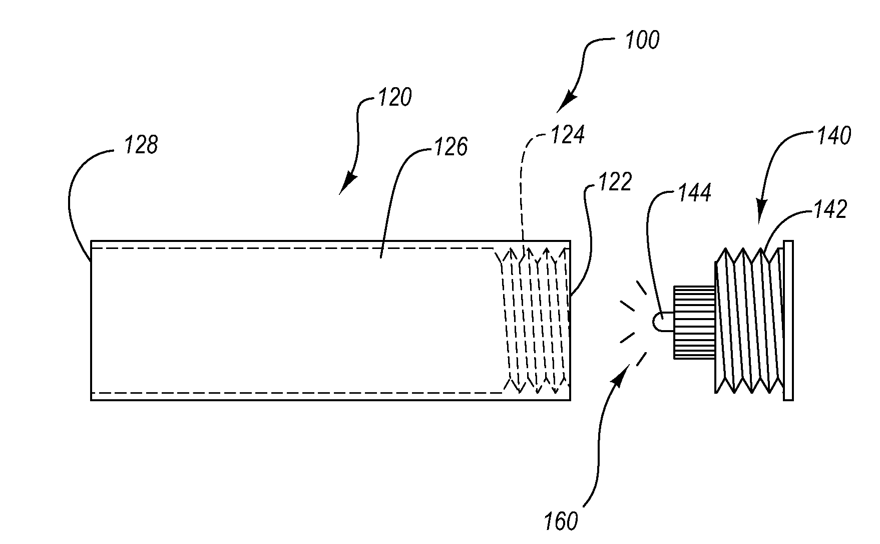
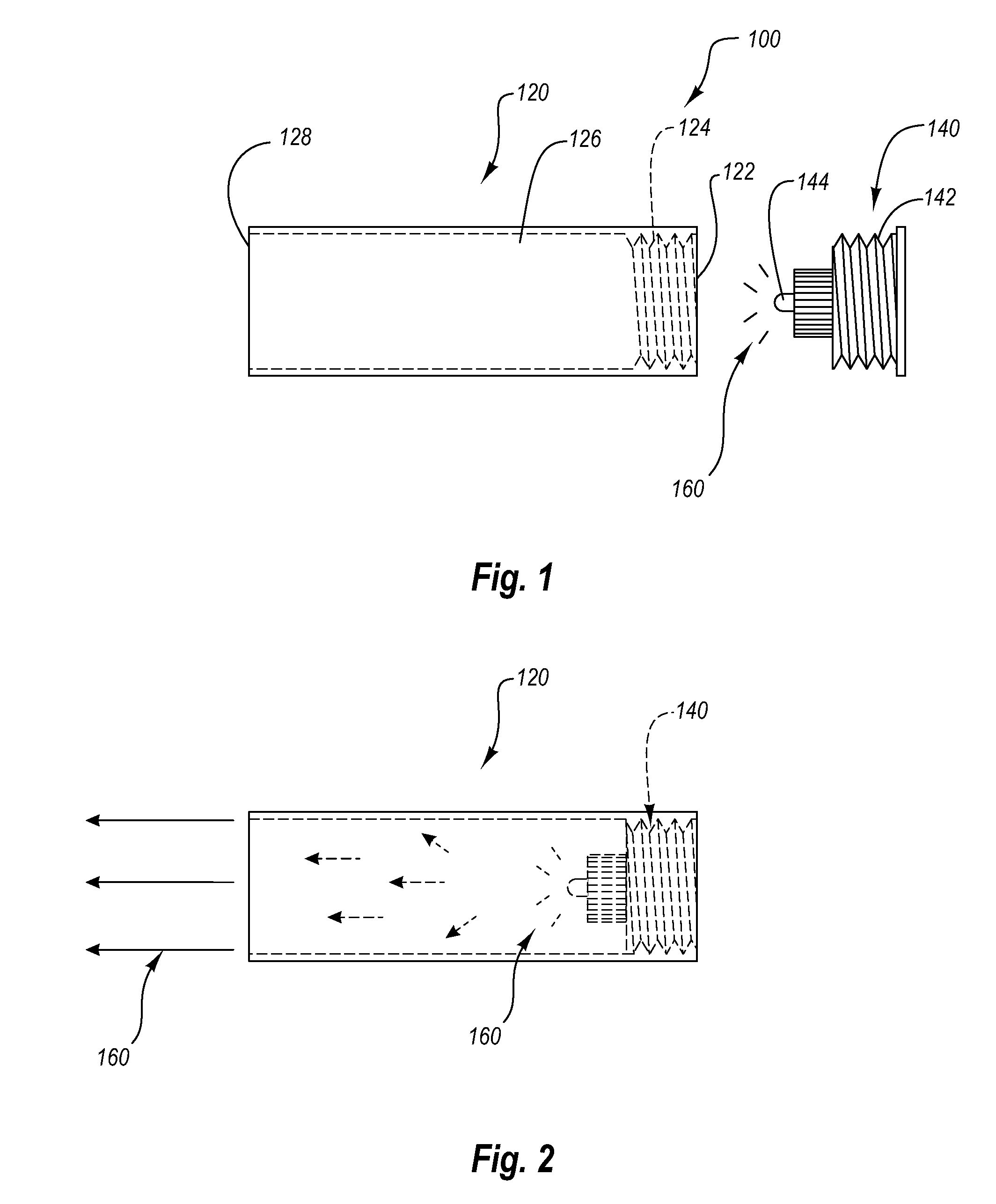
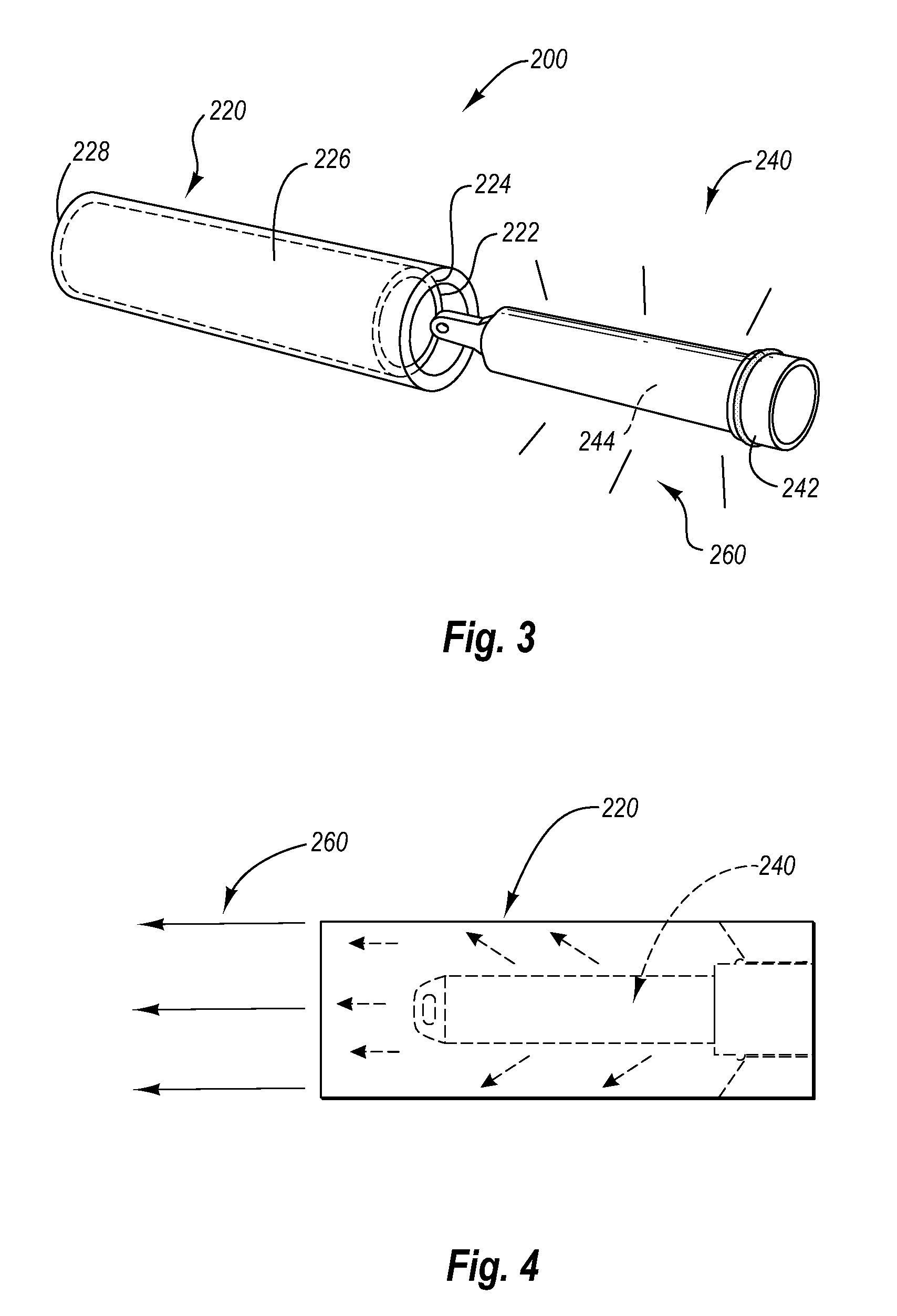
[0027]Reference is next made to FIG. 3, which illustrates a profile view of a discrete optical correlation system in accordance with the present invention, wherein the system is illustrated in a disassembled configuration. The system is designated generally at 200. The system 200 includes an optically opaque hollow module 220 and a chemical illumination system 240. The illustrated chemical illumination system 240 is a conventional glow stick or CYALUME™ that utilizes a contained chemical composition to generate illumination in response to a particular trigger. The illumination system 240 includes a contained chemical composition 244 surrounded by a translucent cover and cap 242. The contained chemical composition 244 transmits light 260 through the translucent cover and cap 242 in a dispersed and / or diffused optical pattern. Various other chemical illumination systems may also be utilized in the system 200 in accordance with the present invention including but not limited to KRILL™ ...

third embodiment

[0031]Reference is next made to FIG. 5, which illustrates a profile view of a discrete optical correlation system in accordance with the present invention, wherein the system is illustrated in a disassembled configuration. The system includes an elongated transparent optical illumination system 300 and an optically opaque sleeve 350. The optical illumination system includes an elongated transparent member 320 and a portable illumination system 340. The elongated transparent member 320 is shaped in the form of a hollow cylinder with two open sides. The elongated transparent member 320 is composed of a transparent or translucent material such as plastic. The illustrated portable illumination system 320 is an electrically based system, but it will be appreciated that other types of portable illumination systems may also be used in accordance with the present invention. The portable illumination system 340 includes an illumination source 344 that produces illumination 360. The portable ...


PUM


Abstract

The present invention relates to a discrete optical correlation system. One embodiment of the present invention includes a portable electrical illumination system and an optically opaque hollow module, configured to releasably couple to the portable electrical illumination system in a manner such that when the portable electrical illumination system is activated, the system produces a discrete correlated or focused illumination output. The portable electrical illumination system further includes a light emitting diode, a power source, a switch, and a coupling mechanism. The optically opaque hollow module further includes at least two openings, a hollow internal region, an optically opaque outer surface, and a coupling mechanism disposed on at least one of the at least two openings.

Description

FIELD OF THE INVENTION[0001]The invention generally relates to portable optical illumination systems and accessories. In particular, the present invention relates to a discrete optical correlation system.BACKGROUND OF THE INVENTION[0002]Portable illumination systems may be used to provide illumination in both dispersed and focused light patterns. Dispersed illumination systems allow light to transmit in a variety of directions, while focused illumination systems contain or focus light in a particular direction. Depending on the application and light source, a user may require dispersed light, focused light, or a combination thereof.[0003]Various electrical illumination systems mimic the dispersed illumination characteristics of chemical light sticks. These systems involve transmitting an electrically powered light source into a translucent member such that the illumination from the light source is transmitted through the translucent portions of the translucent member. These electric...

Claims


Application Information

Patent Timeline
IPC IPC(8): G02B26/08
CPCG02B27/20
Inventor KENNEDY, GREGORYKENNEDY, DOUGLAS
Owner KENNEDY GREGORY
Why Eureka
Try Eureka