Scroll compressor with bifurcated flow pattern

a compressor and flow pattern technology, applied in the direction of positive displacement liquid engines, piston pumps, liquid fuel engines, etc., can solve the problems of gas entrainment an excessive amount of oil, insufficient amount of oil in the compressor, gas vortex or turbulence, etc., and achieve the effect of reducing the amount of oil entrainmen

Active Publication Date: 2007-12-25
TRANE INT INC
View PDF13 Cites 33 Cited by
  • Summary
  • Abstract
  • Description
  • Claims
  • Application Information

AI Technical Summary

Benefits of technology

[0037]One or more of the above-listed objects of the invention are provided by a scroll compressor wherein two gas passageways are defined between the stator and a compressor shell or between the stator and a motor sleeve. Gas is directed through the compressor shell in a bifurcated flow pattern that reduces the velocity of gas flowing adjacent to an oil sump at the bottom of the shell, which helps reduce the amount of oil entrainment.

Problems solved by technology

The oil may eventually return to the compressor through a suction inlet of the compressor shell; however, if the discharged gas entrains an excessive amount of oil, the compressor may be left with an insufficient amount of oil in the sump.
Various conditions can cause the gas to entrain an excessive amount of oil.
Also, a protruding counterweight or other irregularity at the lower end of the rotor may create a gas vortex or turbulence that can agitate the oil in the sump.
Keeping the gas flow completely away from the oil sump may reduce oil entrainment but may also create an overheating problem within the motor.
As a result, the motor may overheat.

Method used


Image

  • Scroll compressor with bifurcated flow pattern
  • Scroll compressor with bifurcated flow pattern
  • Scroll compressor with bifurcated flow pattern

Examples


Embodiment Construction

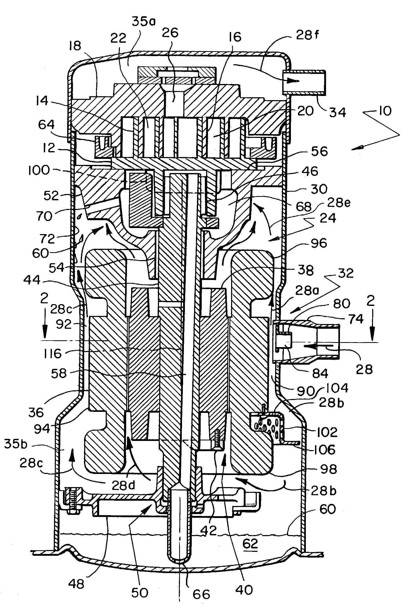
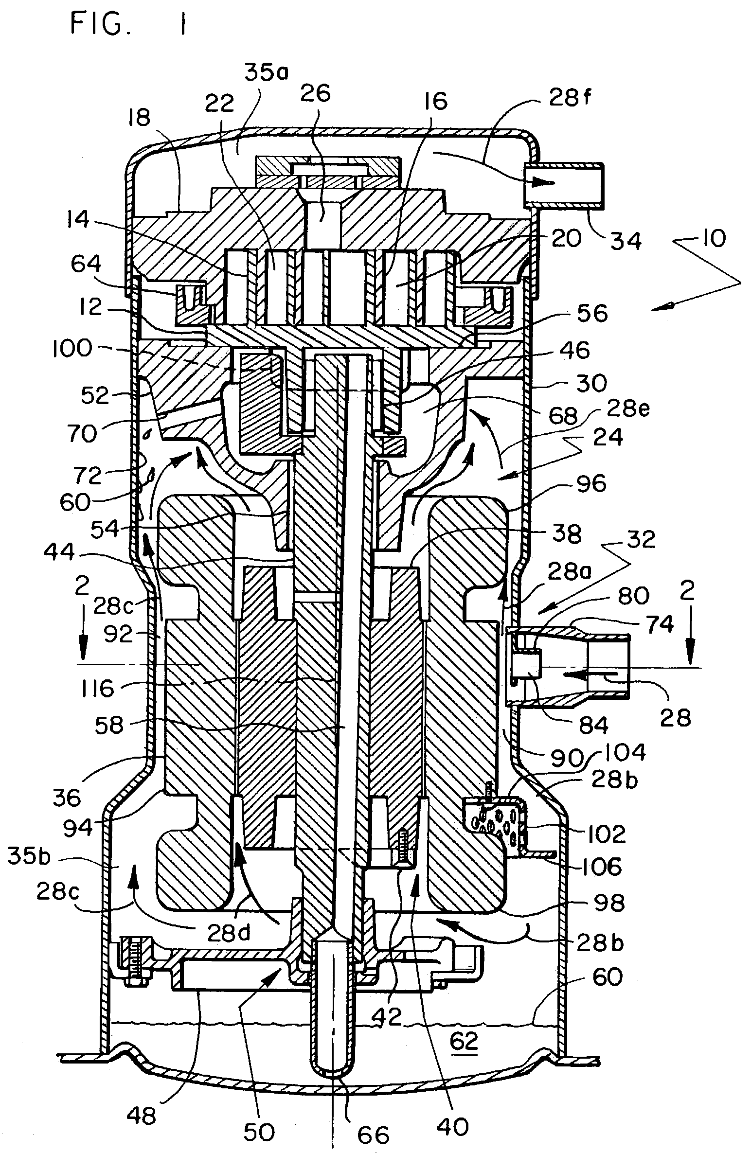
[0055]FIGS. 1 and 2 show cross-sectional view of a scroll compressor 10 having gas and oil flow patterns that minimize oil entrainment. It should be noted that the terms, “oil ” and “lubricant” both refer to any fluid that helps reduce frictions.

[0056]Scroll compressor 10 comprises a driven scroll member 12 with a scroll wrap 14 that interleaves a similar scroll wrap 16 of another scroll member 18. The two scroll wraps define several compression chambers, such as chambers 20 and 22, for compressing a refrigerant or other type of gas, air for instance. A motor 24 drives scroll member 12 in an orbital motion relative to scroll member 18. The relative movement between the two scroll members forces the compression chambers to spiral toward a discharge opening 26 of scroll member 18. As the compression chambers approach discharge opening 26, the volumes of the compression chambers decrease, thereby compressing the gas trapped within the chambers. As will be described in more detail below...


PUM


Abstract

A scroll compressor includes various features that promote a bifurcated flow pattern of gas through a compressor shell to reduce oil entrainment. After entering the shell, some gas travels upward, which reduces the volume of gas traveling downward toward an oil sump. To accomplish this, the compressor's motor can be surrounded by a sleeve having upper and lower apertures for directing the flow to the motor's upper and lower stator end turns. In some embodiments, a suction inlet is strategically positioned relative to two gas passageways that are between the stator and the compressor shell. The inlet's position is such that one passageway receives incoming gas and divides the flow in opposite directions: upward and downward. The other passageway only conveys the gas upward. In addition, a suction baffle, a diffuser, a streamlined counterweight and/or a suction line oil trap can also help promote gas/oil separation or minimize oil entrainment.

Description

BACKGROUND OF THE INVENTION[0001]1. Field of the Invention[0002]The present invention relates to scroll compressors and more specifically to structure that helps direct and separate the flow of gas and lubricant through the compressor.[0003]2. Description of Related Art[0004]Scroll compressors typically comprise two facing scroll members that are contained within a compressor shell. Scroll wraps on each scroll member interleave each other to create a series of compression chambers between the wraps. Proper relative movement between the scroll members cyclically recreates compression chambers along the outer perimeter of the scroll members, where suction gas enters, and subsequently forces the chambers to spiral inward. As the chambers approach the center of the scroll members, the volume of each chamber decreases, which compresses the gas trapped within the chambers. Upon reaching the center of the scroll members, the compressed gas is discharged from the compressor shell for use.[0...

Claims


Application Information

Patent Timeline
Patent Type & Authority Patents(United States)
IPC IPC(8): F04B39/06F01C1/063F04B35/04F04C18/02F04C23/00F04C29/02F04C29/04
CPCF04C29/045F04C29/026F04C23/008F04C18/0215
Inventor WEHRENBERG, CHRIS A.SULLIVAN, BRIAN T.SMERUD, SCOTT J.
Owner TRANE INT INC
Why Eureka
Try Eureka