Vacuum cleaner

a vacuum cleaner and vacuum technology, applied in the field of electric vacuum cleaners, can solve the problems of significant reduction of the overall suction force, significant disturbance of the suction flow, and increase the overall size of the vacuum cleaner itself, so as to prevent the deterioration of the suction force, increase the overall size of the vacuum cleaner, and maintain the suction performance

Inactive Publication Date: 2007-12-25
PANASONIC CORP
View PDF10 Cites 2 Cited by
  • Summary
  • Abstract
  • Description
  • Claims
  • Application Information

AI Technical Summary

Benefits of technology

[0004]It is, therefore, an object of the present invention to provide a vacuum cleaner capable of maintaining suction performance thereof by preventing deterioration of a suctioning force without increasing the size thereof.

Problems solved by technology

Under such arrangement, however, the dirt particles collected in dirt collection chamber 31 via air inlet 32 adhere to filter 36, resulting in a significant disturbance of the suction flow, which in turn significantly reduces the overall suction force.
However, such enlarged filter entails a problem of increasing the size of dirt collection chamber 31 and consequently increasing the overall size of the vacuum cleaner itself.

Method used


Image

  • Vacuum cleaner
  • Vacuum cleaner
  • Vacuum cleaner

Examples


Embodiment Construction

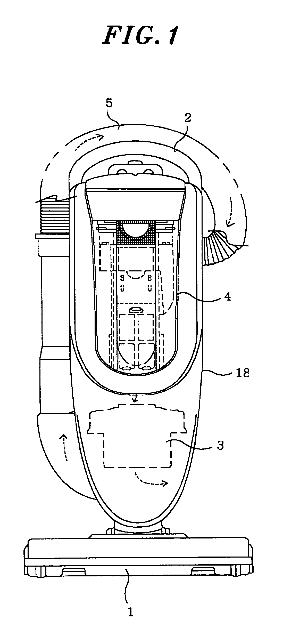
[0036]A preferred embodiment of the present invention will now be described with reference to FIGS. 1 to 6.

[0037]FIG. 1 is a front view of an electric vacuum cleaner in accordance with the preferred embodiment of the present invention. The vacuum cleaner includes suction nozzle 1 through which dirt particles on a surface to be cleaned are suctioned; main body 18 having therein electric blower 3 for creating a suction air stream; handle 2 having a grip portion in an upper portion of main body 18; a dirt collection unit 4, detachably mounted to main body 18, for collecting therein dirt particles; and hose 5 fixed to handle 2, wherein hose 5 communicating with suction nozzle 1 and dirt collection unit 4 provides a suction air stream pathway therebetween. Further provided in main body 18 is an exhaust port (not shown) for discharging an exhaust air stream generated by electric blower 3.

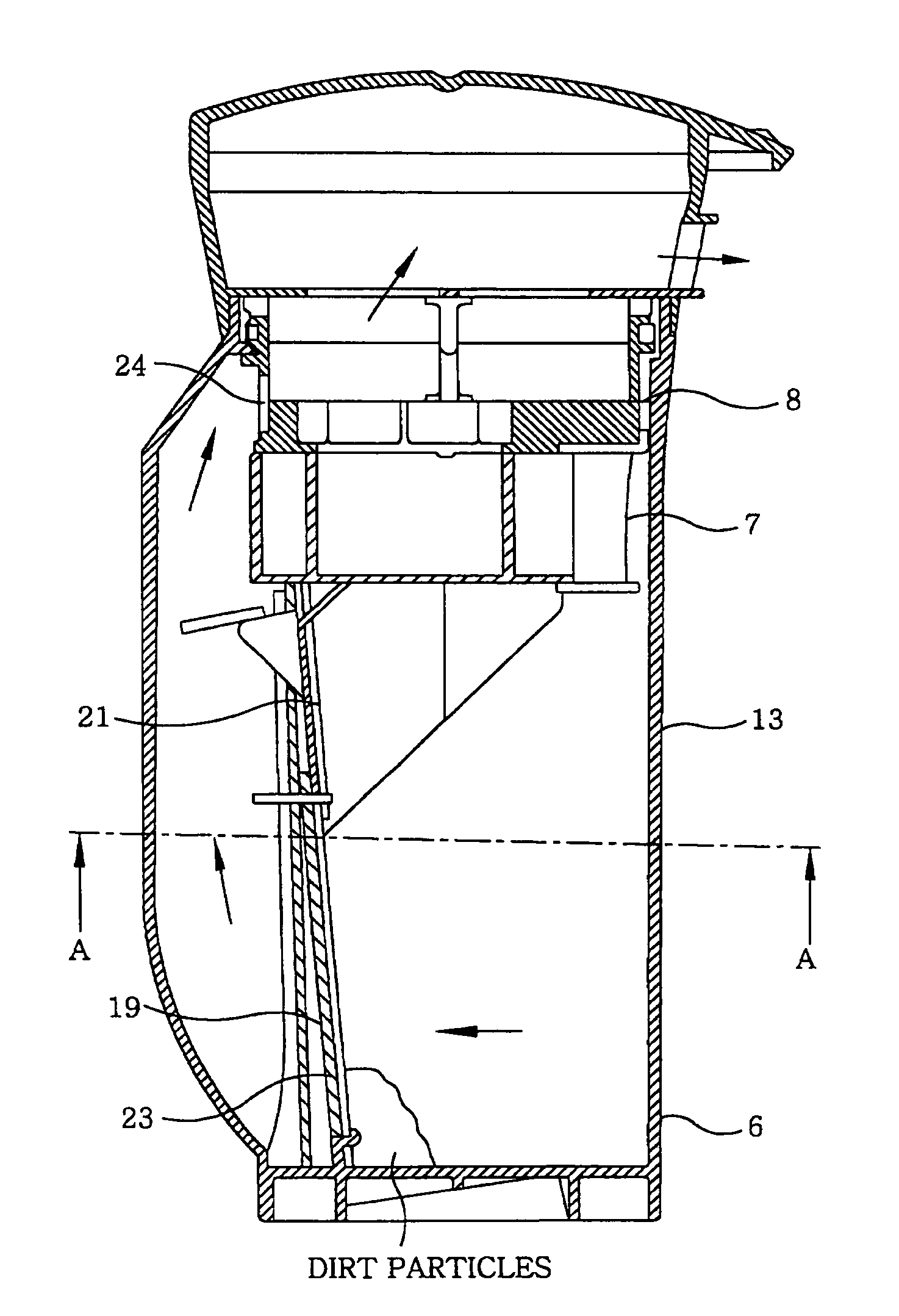
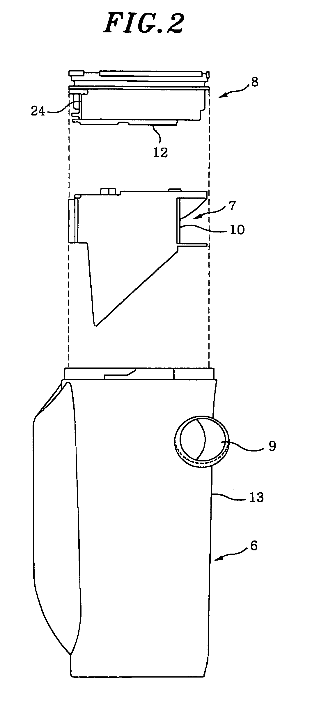
[0038]Referring to FIG. 2, there is illustrated detachably installed dirt collection unit 4 including ...


PUM

PropertyMeasurementUnit
suctionaaaaaaaaaa
sizeaaaaaaaaaa
suctioning forceaaaaaaaaaa

Abstract

An electric vacuum cleaner includes an inlet port through which a suctioned air stream including dirt particles pass and a centrifugal separation member having a substantially circular space therein. The centrifugal separation member has a swirl portion to swirl the dust-laden suction air stream along an inner surface of the centrifugal separation member. By forming swirl passageway between the swirl portion and the inner surface of the centrifugal separation member, the high velocity swirling air stream can be made and consequently an efficiency of separating the dirt particles from the suction air and collecting the dirt particles can be improved.

Description

FIELD OF THE INVENTION[0001]The present invention relates to an electric vacuum cleaner; and, more particularly, to a dirt collection structure of an electric vacuum cleaner.BACKGROUND OF THE INVENTION[0002]Referring to FIG. 7, there is illustrated a conventional electric vacuum cleaner including dirt collection chamber 31 having a bottom surface and air inlet 32 tangentially provided on a side wall of dirt collection chamber 31. Cover 34 is provided to cover upper opening 33 of dirt collection chamber 31 and exhaust port 35 is formed in cover 34. Further, filter 36 is provided to cover upper opening 33 of dirt collection chamber 31. During an operation of electric blower 37, dirt particles are suctioned from suction nozzle 38 and travel into dirt collection chamber 31 via air inlet 32. The dirt particles in the suctioned dirt-laden air stream are centrifugally separated in dirt collection chamber 31, and the dirt-free air stream is exhausted through exhaust port 35 via filter 36 (s...

Claims


Application Information

Patent Timeline
Patent Type & Authority Patents(United States)
IPC IPC(8): B01D45/12A47L9/10A47L9/16
CPCA47L9/165A47L9/1666Y10S55/03
Inventor MORI, HIROSHIODACHI, TORUSUNABA, KENICHIROIMAI, TETSUO
Owner PANASONIC CORP
Why Eureka
Try Eureka